21 installation display unit / platform, 1 technical data, 2 weighing system design – KERN & SOHN KET-TM User Manual
Page 193
KEN-TM / KET_TM-BA-e-1420
193
21 Installation display unit / platform
Installation / configuration of a weighing system must be carried out by a well
acquainted specialist with the workings of weighing balances.
To configure a weighing system you have to call up the service level in the
menu. Here you can change all parameters. For this reason direct access to the
service switch is locked.
For disabling access lock see chap. 21.4.
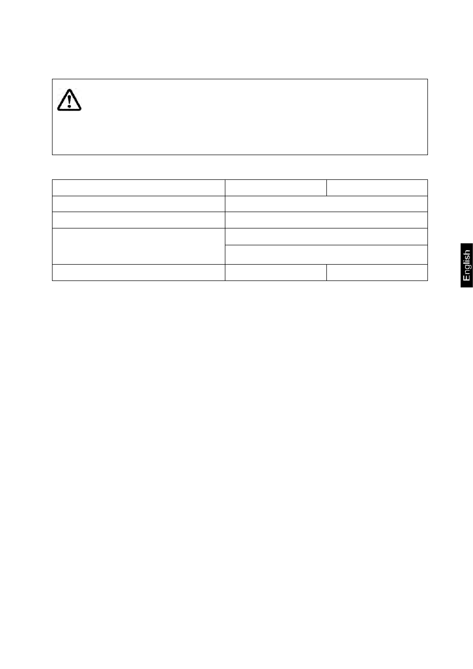
21.1 Technical data
KET-TM
KEN-TM
Supply voltage platform
5 V
Max. signal voltage
19.5 mV
Load cell resistance
min. 80 Ω
max. 1200 Ω
Max number of platforms
2
4
21.2 Weighing system design
The display unit is suitable for connection to any analogue load cell in compliance with
the required specifications.
The following data must be established before selecting a load cell:
•
Weighing balance capacity
This usually corresponds to the heaviest load to be weighed.
•
Preload
This corresponds to the total weight of all parts that are to be placed on the
weighing cell such as upper part of platform, weighing pan etc.
•
Zeroing range
•
Smallest desired display division
•
Verifiable, if required
The addition of weighing scales capacity, preload and the total zero setting range give
the required capacity for the weighing cell.
To avoid overloading of the weighing cell, include an additional safety margin.