Juniper Systems Allegro DAQ User Manual
Page 13
Data Acquisition Expansion Pod 13
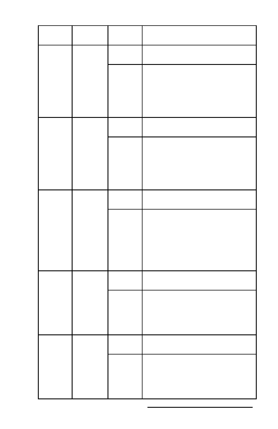
Signal
name
Reference
Direction
Description
PFI
5/AO
SAMP
CLK
D GND
Input
PFI 5—As an input, this pin is a
PFI.
Output
AO Sample Clock Signal—As
an output, this pin is the ao/
SampleClock signal. A high-to-low
edge on AO SAMP indicates that
the AO primary group is being
updated.
PFI
6/AO
START
TRIG
D GND
Input
PFI 6—As an input, this pin is a
PFI.
Output
AO Start Trigger Signal—As
an output, this pin is the ao/
StartTrigger signal. In timed AO
sequences, a low-to-high transition
indicates the initiation of the
waveform generation.
PFI 7/AI
SAMP
CLK
D GND
Input
PFI 7—As an input, this pin is a
PFI.
Output
AI Sample Clock Signal—As
an output, this pin is the ai/
SampleClock signal. This pin
pulses once at the start of each AI
sample in the interval sample. A
low-to-high transition indicates
the start of the sample.
PFI
8/CTR 0
SRC
D GND
Input
PFI 8—As an input, this pin is a
PFI.
Output
Counter 0 Source Signal—As an
output, this pin is the Ctr0Source
signal. This signal reflects the
actual source connected to the
general-purpose counter 0.
PFI
9/CTR 0
GATE
D GND
Input
PFI 9—As an input, this pin is a
PFI.
Output
Counter 0 Gate Signal—As an
output, this pin is the Ctr0Gate
signal. This signal reflects the
actual gate signal connected to the
general-purpose counter 0.