Chapter 5: signal descriptions, I/o connector signal descriptions – Juniper Systems Allegro DAQ User Manual
Page 10
10 User’s Guide
I/O Connector Signal Descriptions
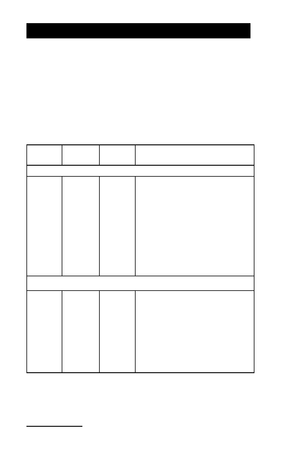
The following table describes the signals found on the I/O
connectors. The information is based on documentation provided in
the National Instruments E Series help file (http://sine.ni.com/nips/cds/
view/p/lang/en/nid/1038).
NOTE: The first two signals (SENSOR EXC and A1) have been
added to the original chart to show the additional functions of the DAQ
Expansion Pod.
Signal
name
Reference
Direction
Description
Addition to the DAQ Expansion Pod
SENSOR
EXC
AO GND Output
Sensor Excitation—This pin
provides up to 200mA excitation
current, driven by the voltage
output of AO channel 0. The
output follows a one-to-one
relationship with the voltage
applied to AO channel 0. Voltage
must be maintained between 0
and 4.8V. Do NOT allow negative
voltages and never exceed output
voltage of 4.8V.
Signal with reduced functionality for the DAQ Expansion Pod
AI <0..6,
8..14>
AI GND
Input
AI Channels 0 through 6 and 8
through 14—You can configure
each channel pair, AI
(i = 0..7), as either one differential
input or two single-ended inputs.
▲
Chapter 5: Signal Descriptions