Juniper Systems Allegro DAQ User Manual
Page 11
Data Acquisition Expansion Pod 11
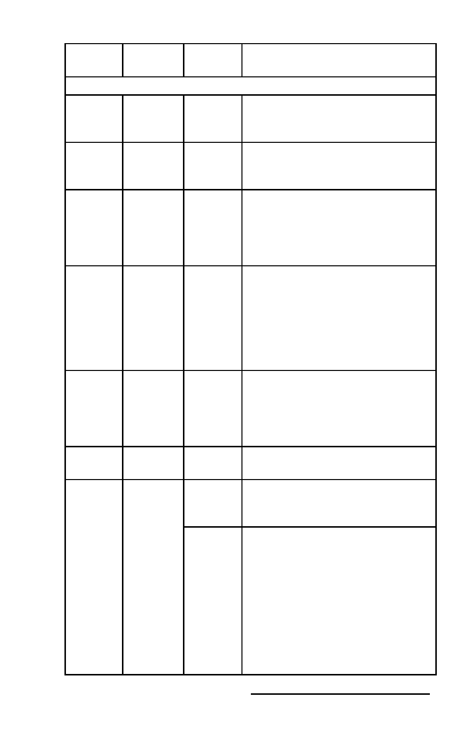
Signal
name
Reference
Direction
Description
Standard National Instruments E Series DAQCard Signals
AI
SENSE
—
Input
AI Sense—This pin is the reference
node for AI <0..15> in NRSE
mode.
AO 1
AO GND Output
Analog Channel 1 Output—This
pin supplies the voltage output of
AO channel 1.
AO
GND
—
AO
Ground
The AO voltages are referenced
to these pins. All three ground
references—AI GND, AO GND,
and D GND—are connected on the
device.
D GND
—
Digital
Ground
These pins supply the reference
for the digital signals at the
I/O connector as well as the +5
VDC supply. All three ground
references—AI GND, AO GND,
and D GND—are connected on the
device.
DIO
<0..7>
D GND
Input or
Output
Digital
I/O
Signals
You can individually configure
each signal as an input or output.
P0.6 and 7 can also control the up/
down signal of general-purpose
counters 0 and 1, respectively.
+5 V
D GND
Output
+5 V Power Source—These pins
provide +5 V power.
PFI 0/AI
START
TRIG
D GND
Input
PFI 0—As an input, this pin is a
programmable function interface
(PFI).
Output
AI Start Trigger Signal—As
an output, this pin is the ai/
StartTrigger signal. In posttrigger
DAQ sequences, a low-to-high
transition indicates the initiation
of the acquisition sequence. In
pretrigger applications, a low-
to-high transition indicates
the initiation of the pretrigger
conversions.