Juniper Systems Allegro DAQ User Manual
Page 12
12 User’s Guide
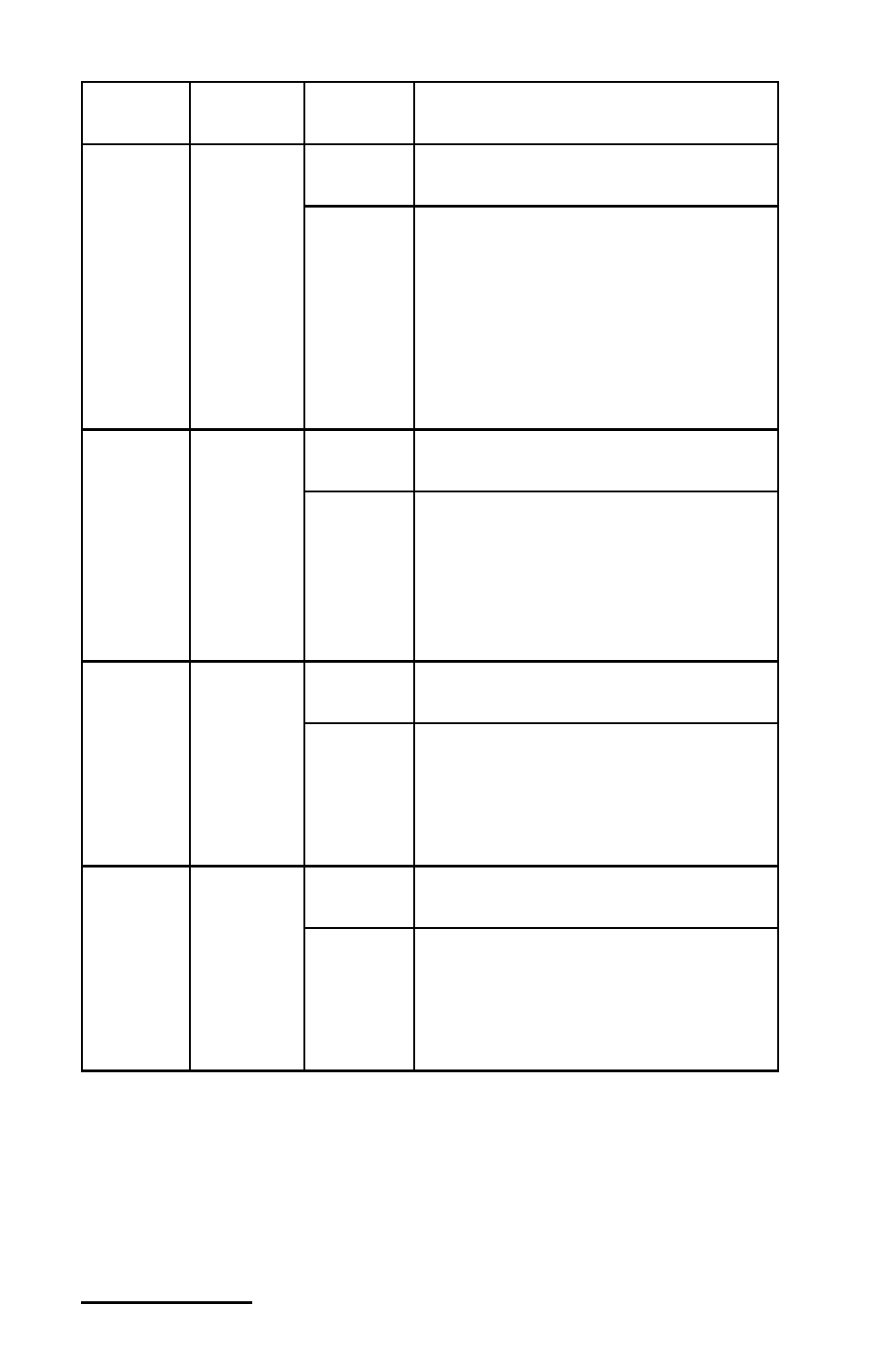
Signal
name
Reference
Direction
Description
PFI 1/AI
REF
TRIG
D GND
Input
PFI 1—As an input, this pin is a
PFI.
Output
AI Reference Trigger Signal—As
an output, this pin is the ai/
ReferenceTrigger signal. In
pretrigger applications, a low-
to-high transition indicates the
initiation of the posttrigger
conversions. AI REF TRIG is not
used in posttrigger applications.
PFI 2/AI
CONV
CLK
D GND
Input
PFI 2—As an input, this pin is a
PFI.
Output
AI Convert Clock Signal—As
an output, this pin is the ai/
ConvertClock signal. A high-to-
low edge on AI CONV indicates
that an A/D conversion is
occurring.
PFI
3/CTR 1
SRC
D GND
Input
PFI 3—As an input, this pin is a
PFI.
Output
Counter 1 Source Signal—As an
output, this pin is the Ctr1Source
signal. This signal reflects the
actual source connected to the
general-purpose counter 1.
PFI
4/CTR 1
GATE
D GND
Input
PFI 4—As an input, this pin is a
PFI.
Output
Counter 1 Gate Signal—As an
output, this pin is the Ctr1Gate
signal. This signal reflects the
actual gate signal connected to the
general-purpose counter 1.