15 connect the ecu – Haltech E6M User Manual
Page 28
22
Check your trigger system thoroughly. An incorrectly wired trigger can cause damage,
usually to the trigger.
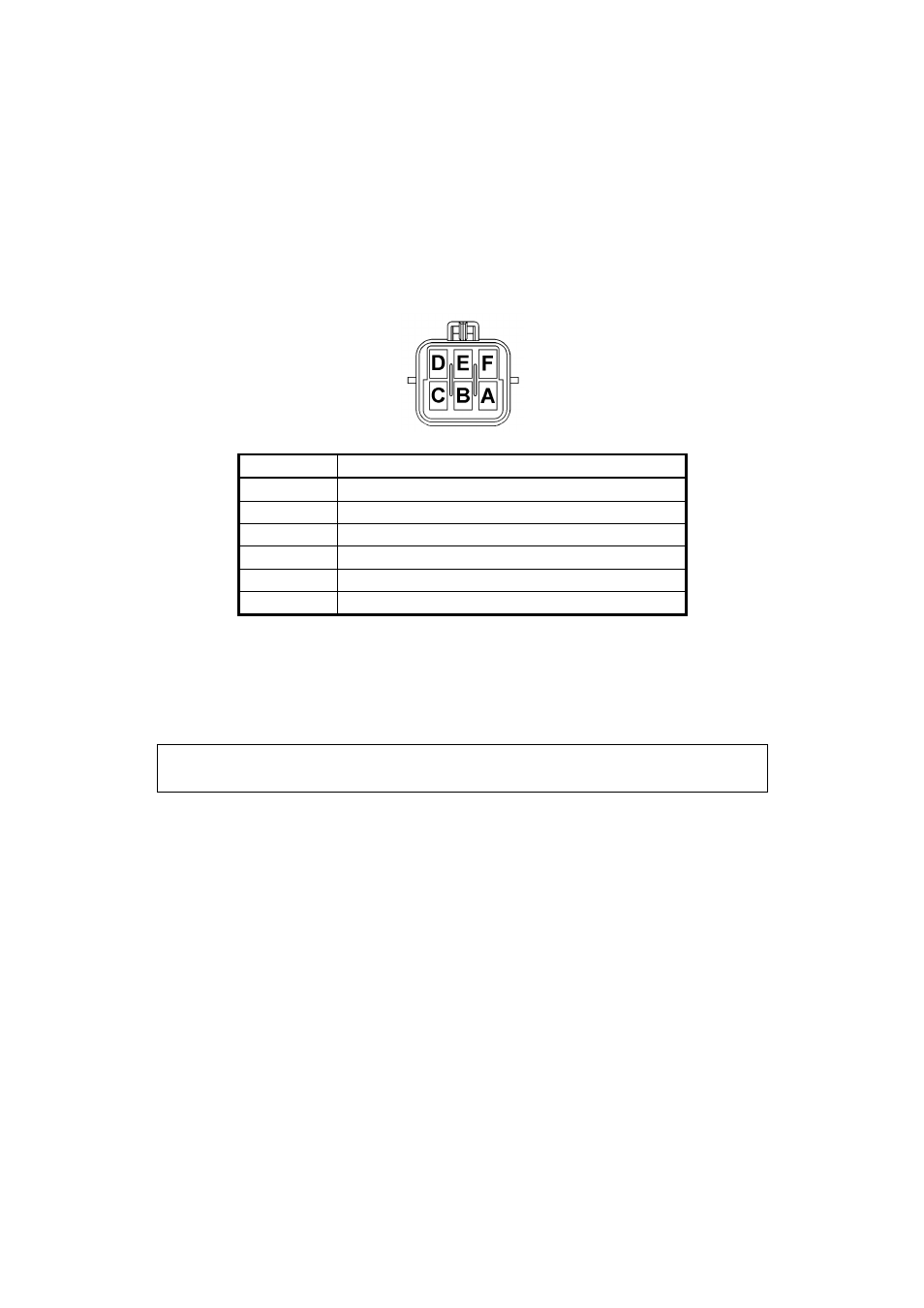
The trigger connector on the Main Harness has six pins. These pins and their connections are
shown in the diagram below. The Secondary (Home) Trigger is used for Direct Fire or
Sequential Applications (See Appendix B). If your wiring harness is of the flying wire type
you should ensure that the trigger wire is shielded and that the shielding is properly grounded
to protect against external interference to the signal from “noise”.
PIN
FUNCTION
A
GROUND
B
MAIN TRIGGER
C
INPUT A (RELUCTOR)
– E6M and E6M-8 Only
D
INPUT B (RELUCTOR)
– E6M and E6M-8 Only
E
HOME
F
13.8 V DC
It is recommended the you read Appendix E, Trigger Interface for more detailed information
on the trigger requirements of the E6H/E6M.
Note: If you are using a motronic sensor read appendix E.3 Motronic Type
Trigger
1.3.15 Connect the ECU
The ECU can now be connected and tested. Be sure to engage the clip on the main connector
this will make sure the main connector parts mate correctly and reduces the mechanical strain
on the connector bodies. The system can now be tested as described in the following chapters.