Appendix e trigger interface, E.1 hall effect trigger – Haltech E6M User Manual
Page 130
124
APPENDIX E
TRIGGER INTERFACE
The Trigger interface is where the E6H and E6M differ in operation. The E6M has an
onboard reluctor adaptor, which means it can be triggered by a reluctor (magnetic coil)
trigger. Reluctor triggers produce a sine like waveform with an amplitude that varies with
engine speed. The E6H can only be triggered by a square wave output. Most Hall effect and
optical triggers produce a square wave output suitable for the E6H.
Note: The E6M is capable of accepting both a reluctor (magnetic coil) trigger
and a square wave trigger input. The E6H is only capable of accepting square
wave triggers.
E.1 Hall Effect Trigger
The E6H/E6M ECU has been designed to trigger from a square wave signal. Hall effect and
optical triggers are the most common form of square wave triggers, other square wave triggers
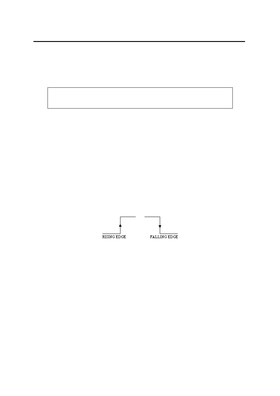
are available but are not so common. The square wave trigger signal must switch from a
‘low’ of zero volts (ground) to a ‘high’ of between 5 and 15 volts. The exact value of the
‘high’ voltage is not important because it is the transition from ‘low’ to ‘high’, or ‘high’ to
‘low’, that is used to trigger the E6H/E6M ECU. This transition is referred to as the Trigger
Edge and will be shown in the following illustrations as an upward or downward facing
arrow. An upward facing arrow would indicate that the trigger edge is in the transition from
low to high and this is called a Rising Edge trigger. If the trigger edge occurs on the transition
from high to low, it will be shown as a downward facing arrow, and would be called a falling
edge trigger. See Figure E.1.
Figure E.1
In order for the E6H/E6M to operate correctly a trigger edge must be generated for each
spark. This edge must occur a fixed number of degrees before top dead centre (BTDC) and
must not change. The position of the trigger is given in crankshaft degrees and is called
Trigger Angle. In addition there should not be any variation in the trigger angle between
cylinders. The E6H/E6M can be set by the user to have its trigger edge occur between 60° and
100° BTDC.
In the example shown in figure E.2a the trigger occurs on a rising edge at 70° BTDC. The
second transition, from high to low, could occur any time after the rising edge. In some
installations the second transition will coincide with 10° BTDC or TDC itself, or it could
happen as close as a few degrees after the trigger edge. This second edge will have no effect
on the correct operation of the E6H/E6M ECU. It is only the position of the triggering edge
that is of importance.