Install and connect optional idle speed motor, Install and connect any optional outputs, 14 connect the trigger sensor – Haltech E6M User Manual
Page 27
21
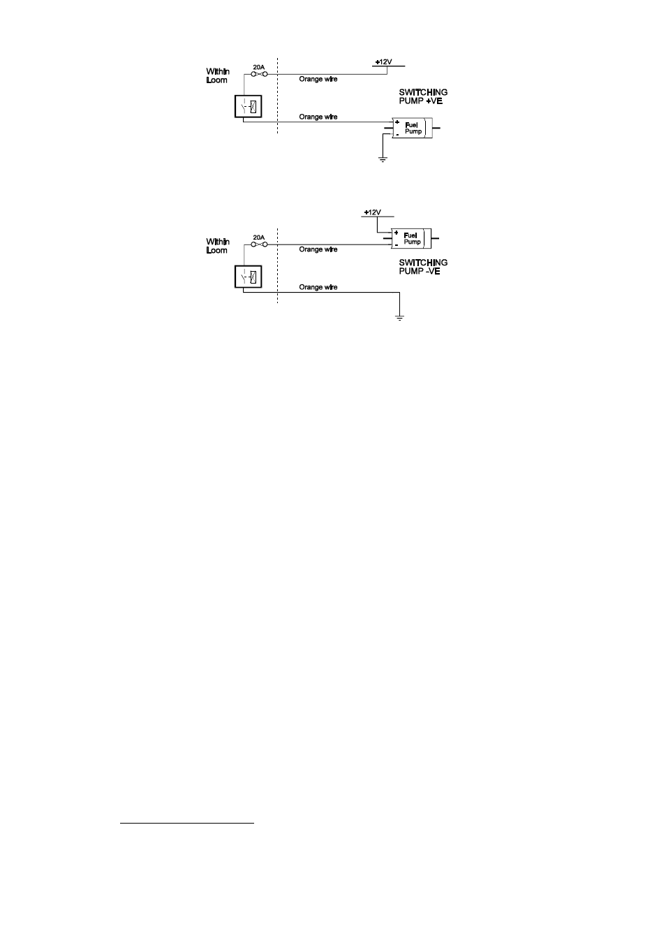
Example 1: Connecting to the positive side of the fuel pump.
Example 2: Connecting to the negative side of the fuel pump.
It does not matter which example is used, both will operate correctly. Note that the orange
wires are connected internally within the loom when the relay is closed. As a result it does not
matter which orange wire is used to connect to the fuel pump.
1.3.12. Install and connect Optional Idle Speed Motor
If you are not using the Idle Speed Control, tie the loom connector back neatly in the engine
bay. If the engine has a suitable Idle Speed Motor then you may connect it to the wiring loom,
otherwise you can install a Haltech supplied idle air control motor. For details on how to
install and plumb the Idle Speed Motor, see Chapter 14.
1.3.13. Install and connect any Optional Outputs
If you are planning to use any of the Programmable Optional Outputs, install and connect
them now. Depending on what options you are using, the wiring will be different. For details
on wiring your particular options, refer to Section 4, E6H/E6M Outputs.
1.3.14 Connect the Trigger Sensor
The E6H/E6M requires one trigger for each ignition event. For example, a V8 engine will
require 4 triggers per engine revolution.
Hall Effect and Optical triggers need three connections each - ground, power and the signal.
E6M AND E6M-8 ONLY
Reluctor (magnetic core) trigger devices for either the main Trigger or the Home
signal require two wires each which connect to form an isolated loop to detect a
trigger. Some triggers need a series resistor on the power line in order to limit current.