Control throws, Balance your model – Great Planes Super Skybolt 60 Kit - GPMA0170 User Manual
Page 68
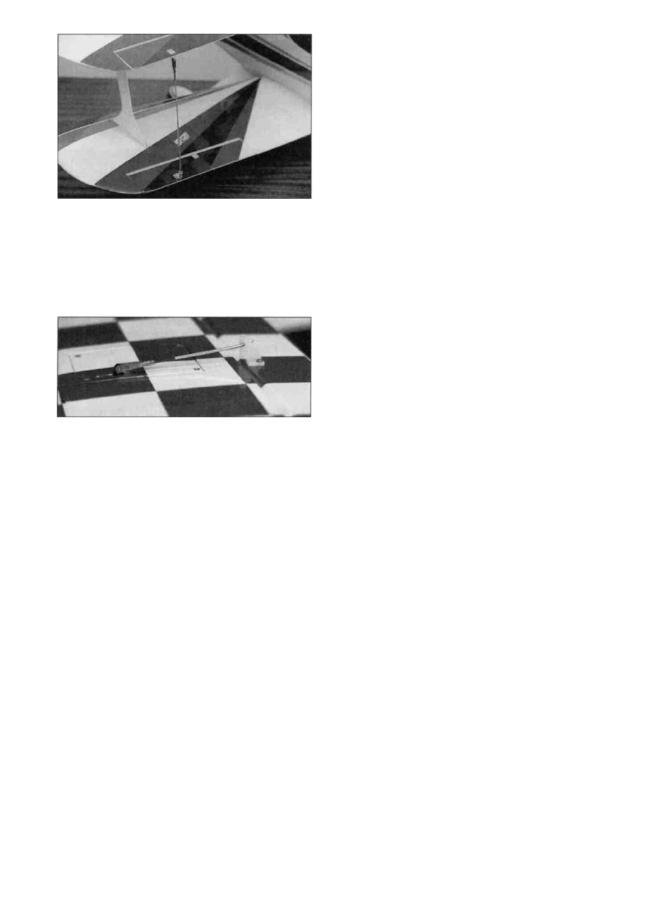
and slide a solder clevis (METAL024) onto each
wire Hold the solder clevises along side each
bottom wing control horn so the solder clevis pin is
near the control horn hole Mark where to cut off
the wires Remove the wires, cut them off, and
solder the clevises into place
D 6 If you are using two aileron servos, make the
aileron pushrods by screwing a nylon clevis (a
metal one is pictured) onto the remaining two 12"
threaded rods Hook up the clevises to the aileron
horns and, with the aileron servos in their neutral
positions, mark where the wires cross the holes in
the control horns Make a Z-bend at the marks,
and cut the excess wire off Test the operation of
the ailerons to make sure they operate smoothly
Enlarge the slots in the hatch if necessary to
achieve the proper control deflection (see chart
below) Hook up the slave struts, and check the
top wing aileron movement Make sure they move
smoothly, with no control "slop".
CONTROL THROWS
The following control throws are recommended for
your first flights They are measured at the widest
part of the control surface.
Low Rate High Rate
ELEVATOR: 7/8" 1-3/8"
RUDDER: 1-1/2" As much as possible
AILERONS: 5/16" 1/2"
BALANCE YOUR MODEL
NOTE: This section is VERY important
and must not be omitted! A model that
is not properly balanced w i l l be
unstable and possibly unflyable.
D 1 Accurately mark the balance point on the
BOTTOM of the top wing The balance point is
shown on the plan (CG), and is located 2-3/4"
(70mm) behind the top wing leading edge at rib T7
This is the balance point at which your model
should balance for your first flights Later, you may
wish to experiment by shifting the balance up to
3/8" (10mm) forward or back to change the flying
characteristics Moving the balance forward may
improve the smoothness and arrow-like tracking,
but it may then require more speed for takeoff and
make it more difficult to slow down for landing.
Moving the balance aft makes the model more
agile, with a lighter and snappier "feel" If you move
the balance aft, the elevator will have more
authority, possibly resulting in a plane that is too
maneuverable If this happens, you should reduce
the maximum elevator throw slightly In any case,
do not balance your model outside the
recommended range.
D 2 Balance the airplane with the fuel tank
empty If it balances outside the "balance range,"
you must either shift the location of radio
components or add weight to the nose or tail until it
balances within the range NOTE: Nose weight
may be easily installed by using a "Spinner
Weight" (available in assorted weights, up to 2
ounces), or by gluing strips of lead into the engine
compartment Tail weight may be added by using
"stick-on" lead weights, and, later, if the balance
proves to be OK, you can open the fuse bottom
and glue these in permanently
- 6 8 -