Decisions you must make now – Great Planes Super Skybolt 60 Kit - GPMA0170 User Manual
Page 5
DECISIONS YOU MUST MAKE NOW
ENGINE AND MOUNT
The recommended engine for the SUPER
SKYBOLT is a 61* - 90 cubic inch (10 - 15cc)
displacement 2-cycle or a 90 - 1 20 cubic inch
( 1 5 - 2 0 c c ) displacement 4-cycle The
instructions and plans show an OS Max
61(10cc) SF and an OS Max 1 20 (20cc)
Surpass being installed It you are using an
engine other than one of these, be sure to
double check all measurements before gluing or
cutting things that have to do with the engine.
*NOTE: Performance may be marginal if a non-
Schnuerle-ported .60 cu.in. 2-Cycle engine
is used
This kit includes a new Great Planes adjustable
.40 - .70 engine mount (EM4070) that fits most
40 - 61 (2-Cycle) engines and 40 - 70 (4-cycle)
engines If the supplied mount does not fit your
engine, it may be necessary to purchase a
different mount (check with your hobby dealer).
POSSIBLE RADIO
INSTALLATIONS
The Super Skybolt can utilize either one
or two aileron servos We recommend that you
use two aileron servos and build the top wing
with ailerons This is the most maneuverable
configuration and you can always reduce the
control throws to achieve the sensitivity you
desire When using two aileron servos, the
servos are mounted in the bottom wing, directly
in front of the ailerons and control slop is
virtually eliminated If you prefer to use only
one aileron servo, we suggest that you do not
put ailerons on the top wing due to the inherent
top aileron sloppiness The plans show both
methods of construction.
COMMON ABBREVIATIONS USED
IN THIS BOOK AND ON THE
PLANS:
GET READY TO BUILD
Elev = Elevator
Fuse = Fuselage
LE = Leading Edge (front)
LG = Landing Gear
Ply = Plywood
Stab = Stabilizer
TE = Trailing Edge (rear)
" = Inches
Tri = Triangle
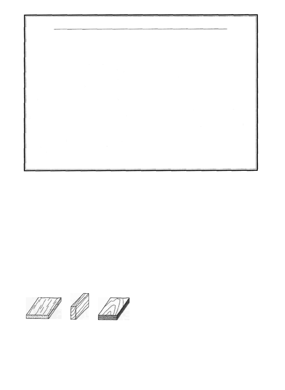
TYPES OF WOOD
D 1 Unroll the plan sheets and reroll them inside
out to help them lie flat.
D 2 Remove all parts from the box As you do,
determine the name of each part by comparing it
with the plan and the parts list at the back of this
book. Using a felt tip pen, write the part name or
size on each piece to avoid confusion later Use
the die-cut part patterns shown on page 6 to
identify the die-cut parts and mark them before
punching out Save all leftover pieces. If any of
the die-cut parts are difficult to punch out, do not
force them' Instead, first cut around the parts with
a hobby knife After punching out the die-cut parts,
use your T-Bar or sanding block to lightly sand the
edges to remove any die-cutting irregularities.
BALSA
BASSWOOD
PLYWOOD
D 3 As you identify and mark the parts, separate
them into groups, such as fuse (fuselage), wing,
fin and stab (stabilizer), and hardware.
- 5 -