Great Planes Super Skybolt 60 Kit - GPMA0170 User Manual
Page 63
Small Nylon
Control Horn
D 2 If you built your Skybolt with four ailerons,
hold the six small nylon control horns
(NYLON03) on the top and bottom wing ailerons in
the positions shown on the plan, and mark the
mounting hole locations Drill 3/32" holes at these
locations. The slave strut horns should be cut off
as shown on the I-strut detail drawing.
D 3. Harden the balsa in the area of all the
control horns by poking several holes with a pin
(on both sides of the control s u r f a c e ) , then
applying thin CA glue. Allow the glue to soak in
and cure. Then sand the surfaces smooth.
D 2 Install the top wing, and make sure it slides
all the way onto the struts Rotate the locking wire
into place against the cabane wire. Mark where the
second screw should be inserted Set it up so you
have to push the wire forward and over the head of
the second screw to be able to remove it. The
head of the second screw should hold the locking
wire in place during flight The locking wire can be
bent slightly, if needed, to make things fit right.
Nut Plate
2-56 x 5/8" Machine
Screw
D 4. Test mount all the control horns with 2-56 x
5/8" machine screws and the nylon nutplates
which were attached to the horns. Remove the
control horns until after the plane is covered.
BALANCE THE AIRPLANE
LATERALLY
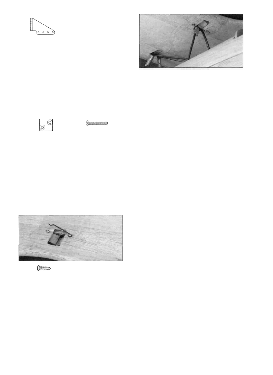
MAKE THE TOP WING LOCK
#2 x 3/8" Screw
SPECIAL NOTE: Do not confuse this
procedure with "checking the C.G." or
"balancing the airplane fore and aft."
Thai very important step will be covered
later in the manual.
Now that you have the basic airframe nearly
completed, this is a good time to balance the
airplane laterally (side-to-side) Here is how to do it:
D 1. Temporarily attach the wing, tail feathers and
the engine (with muffler) to the fuselage.
D 1. Drill a 1/16" hole for the top wing lock
screw. It should be positioned 1/4" behind the aft
edge of the rear top plate and 1/8" outboard of the
T1 rib. Refer to the plans to help you position it.
The main thing is to make sure the screw anchors
into the basswood screw block. Bend the top wing
locking wire (WBNT185) to match the drawing on
the plan Screw it in place with a #2 x 3/8 screw.
Bend the last 3/16" of the wire up away from the
surface of the wing so it will be easier to grab.
D 2. With the wing level, lift the model by the
engine propeller shaft and at the centerline of the fin
(this may require two people). Do this several times.
D 3. If one wing always drops when you lift, it
means that side is heavy. Balance the airplane by
gluing weight to the inside of the other wing tip.
NOTE: An airplane that has been laterally balanced
will track better in loops and other maneuvers.
- 6 3 -