Strengthen and fuel proof the nose, Final hook-ups, Wing seating – Great Planes Super Skybolt 60 Kit - GPMA0170 User Manual
Page 67
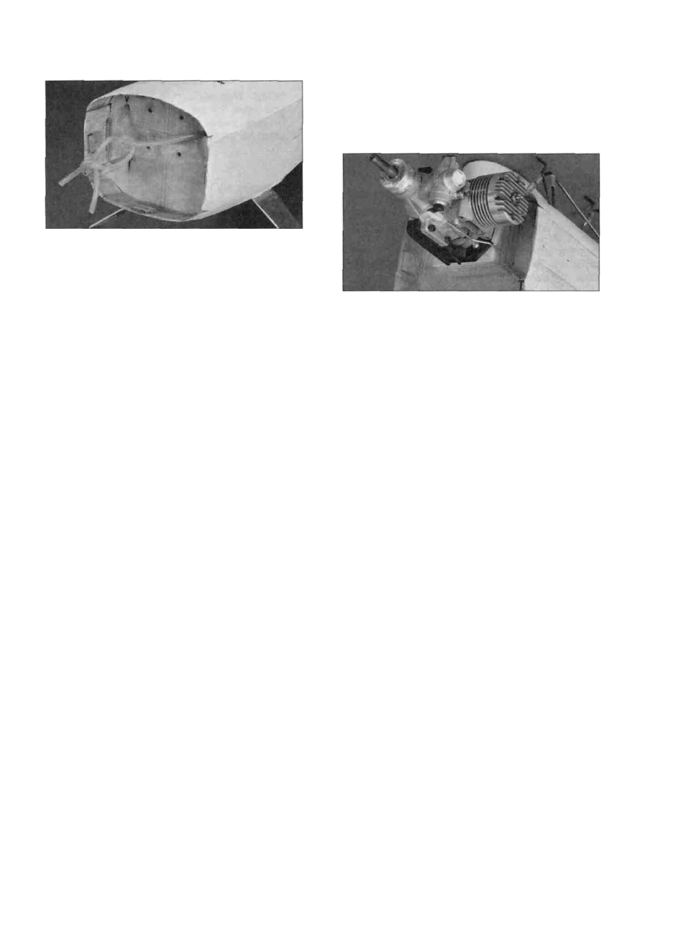
STRENGTHEN AND FUEL PROOF
THE NOSE
D 1. Remove the engine and mount, and tie up the
fuel tubes to keep them out of the way. Apply a
liberal coat of polyester or epoxy resin to all the
exposed wood surfaces. Also apply the remainder
of the fiberglass tape around the inside of the nose.
Apply more resin to thoroughly "wet" out the tape.
This will greatly strengthen the nose overhang. You
may also fuel proof the exposed wood around the
inside of the wing saddle if you desire.
FINAL HOOK-UPS
D 1. Reinstall the engine, cowl, propeller, spinner,
battery, receiver and the switch. Attach both wings
to the fuselage. Screw the nylon control horns
back onto all the control surfaces.
D 2. Hook up the throttle pushrod. Due to the tight
space requirements when using a muffler inside
the cowl, the throttle pushrod may need to be run
around the muffler. The photo above shows a
typical installation when using an OS .61 SF and a
Pitts Style muffler.
WING SEATING
D 1.Apply 1/16" thick x 1/4" wide foam wing
seating tape to the wing saddle area to seal the
wing/fuse Joints.*
*NOTE: An alternate method of sealing
the wing/fuse joint is to use "silicone
bathtub sealer." This is an excellent
method, used by many experts because
it results in a permanent and nearly
perfect wing saddle joint. Briefly, the
technique is as follows:
1. Cover the top of the bottom wing
center section with waxed paper or
plastic kitchen wrap. Pull out all
wrinkles, and tape it to the wing.
2. Squeeze out a bead of silicone sealer
onto the wing saddle area.
3. Lay the wing in the saddle and push
down gently. The excess silicone sealer
will squeeze out.
4. Allow to dry without disturbing for at
least 24 hours.
5. Remove the tape. Then remove the
wing from the saddle (leaving the waxed
paper or plastic wrap in place). 6. Gently
pull the waxed paper or plastic wrap
away from the sealer.
7. Using a new single-edge razor blade,
trim the sealer along the inside and
outside edges of the fuselage.
D 3. Make the rudder pushrod using the remaining
34" threaded wire (WIRES17) and a nylon clevis
(NYLON17). Cut seven 1/4" long inner pushrod
tube spacers, and slide them onto the wire. Space
them about 2" apart along the middle part of the
wire, and screw the nylon clevis onto the threaded
end. Slide the wire into the outer tube that was
installed earlier, and attach the clevis up to the
rudder control horn. Mark where the pushrod wire
crosses the rudder servo horn. Remove the
pushrod, and make a Z-bend at the mark. Unscrew
the nylon clevis, and slide the pushrod wire back
into place from the servo end of the outer tube.
Replace the clevis on the wire, and snap it onto the
control horn. Check the rudder operation to make
sure it is smooth.
D 4. Screw a nylon clevis onto each elevator
pushrod, and hook up the elevators. Check
their operation.
D 5. If you are using four ailerons, assemble the
slave struts by screwing a metal clevis
(METAL013) onto the threaded end of two 12"
threaded wires. Snap the metal clevis onto the
top wing slave strut horns. Tape both the top and
bottom wing ailerons in their neutral positions,
- 6 7 -