Great Planes Super Skybolt 60 Kit - GPMA0170 User Manual
Page 17
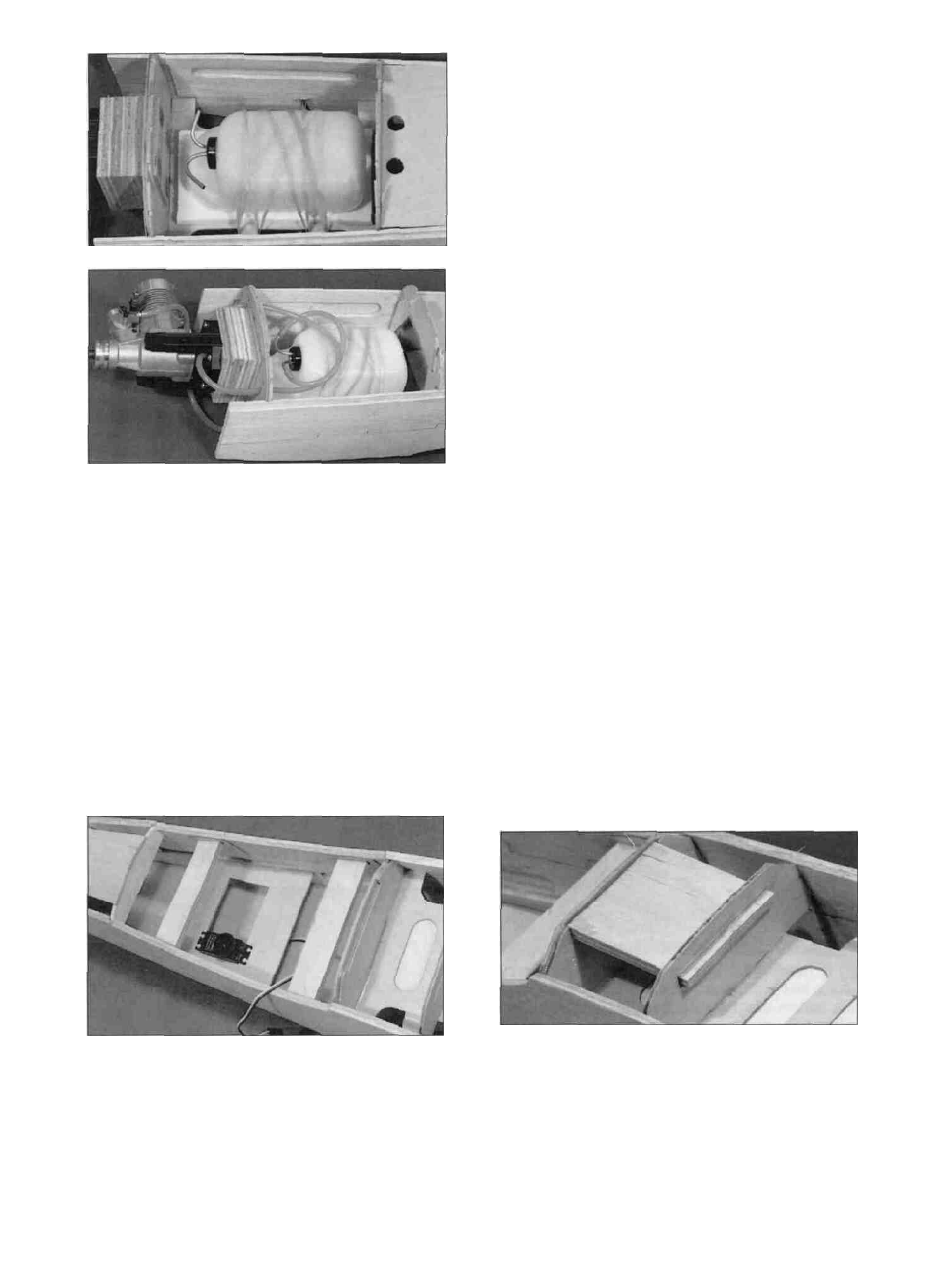
possible. Make sure you will still be able to install
and work on the servo linkages. These servo
positions are not critical, but will help you balance
the plane without using extra weight. The die-cut
1/8" ply servo tray (SKY6W10) is designed to fit in
the doubler lightening hole for most installations,
but will have to be cut down in width to fit towards
the rear of the plane. It can be glued just below
the lightening hole when it needs to be installed
farther forward as shown in the photo. Check your
servos to make sure they will fit into the tray and
are not held off the tray by the cockpit bottom.
Securely glue the tray in place.
D 3. Install the fuel tank using four #64 rubber
bands (not included) as shown in the photo.
Determine where the fuel and vent tubes should
pass through the firewall to match up with your
particular engine. Drill a 1/4" hole for each tube to
pass through the firewall. The larger holes will
allow you to seal around the tubes with silicone
bathtub sealer. Install the fuel tubing, but be sure
to leave a couple extra inches for good measure.
Mark on the front of the firewall which tube is fuel
and which is the vent.
D 5. Determine the location where the throttle
pushrod (not included) will pass through F1.
Normally, a solid wire pushrod will work fine for the
throttle pushrod. Drill a 3/16" hole (or whatever
size you need) in the firewall for the throttle
pushrod guide tube. Cut the outer guide tube to
length and roughen the outside of the tube with
medium grit sandpaper. Slide the tube into place
and glue it with thin and then thick CA. Refer to the
plans to get an idea of how to route the pushrod.
D 4. Determine where your servos should be
mounted. If you are using a lighter engine (.61 -
.75 2-cycle) the servos should go as far forward as
practical. If you are using a heavy engine (1.20
4-cycle) the servos should go as far back as
D 6. Locate the 1/4" x 2-3/4" x 3" ply landing
gear plate (SKY6F30) and test fit it in place
between LG-1 and LG-2. NOTE: The grain
should run from LG-1 to LG-2. Enlarge the slots
if necessary to get the plate to fit. When satisfied
with the fit, securely epoxy the plate in place.
17-