Trigger commands, Sd, mt, ga, te, tr, tl, sa, Sd start delay time [ index 0x211a or 0x2412 – Flintec DAD 141.1 User Manual
Page 50: Mt measuring time [ index 0x210e or 0x2410, Te trigger edge [ index 0x2402 or 0x211c, Tr software trigger [ index 0x2062, Trigger commands – sd, mt, ga, te, tr, tl, sa
DAD 141.1 Technical Manual, Rev. 2.2 - February 2014
Page 50 of 54
10.13. Trigger Commands
– SD, MT, GA, TE, TR, TL, SA
Note: All changes to the trigger commands have to be stored in the EEPROM using the WP command. See
chapter 10.12.
10.13.1. SD Start Delay Time
[
Index 0x211A or 0x2412
]
This command defines a time delay between the trigger and the start of the measurement.
Setting range: 0 ms to 500 ms.
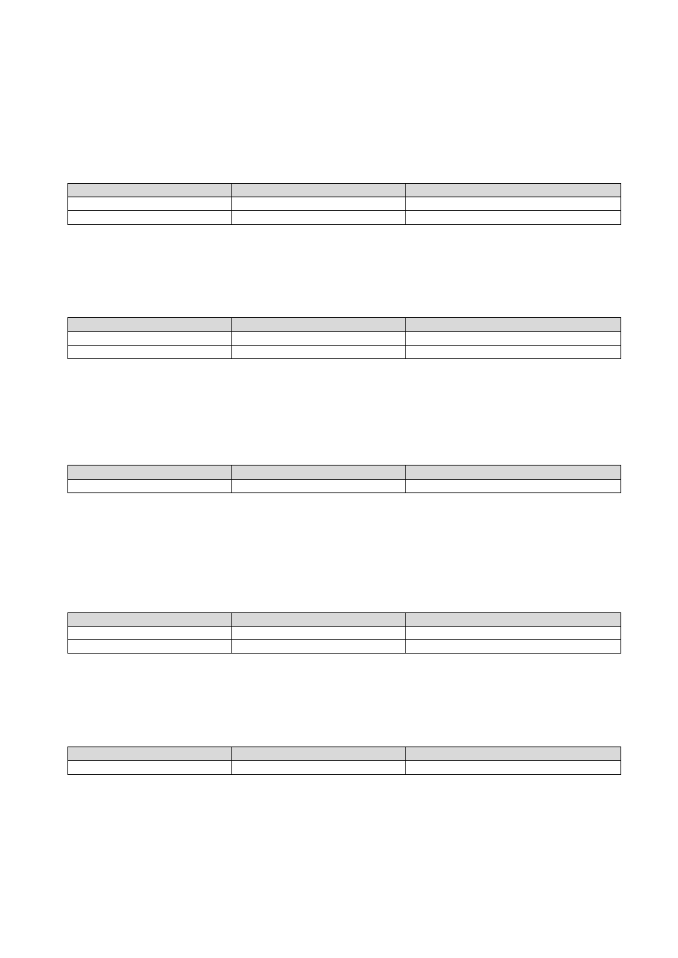
Master (PC / SPS) sends
Slave (DAD 141.1) responds
Meaning
SD
S+00100
Request: SD = 100 ms
SD 200
OK
Setup: SD = 200 ms
Default setting: SD = 0 ms; time plot of a typical checkweigher cycle see below
10.13.2. MT Measuring Time
[
Index 0x210E or 0x2410
]
This command defines the measuring time for the averaged measurement result.
Setting range: 0 ms to 3000 ms.
Master (PC / SPS) sends
Slave (DAD 141.1) responds
Meaning
MT
M+00100
Request: MT = 100 ms
MT 500
OK
Setup: MT = 500 ms
Note: The setting MT = 0 disables the trigger function and the averaging.
Default setting: MT = 0 [= trigger function disabled]; time plot of a typical checkweigher cycle see below
10.13.3. GA Get Triggered Average Value
[
Index 0x2008 or 0x2028
]
This command reads the measurement result of a measurement cycle. The measurement value has been
averaged according the defined measuring time.
Master (PC / SPS) sends
Slave (DAD 141.1) responds
Meaning
GA
A+001.100
Request: GA = 1100 g
Note: For preventing errors during the read out of the data the register GA has stored the value 99999 at the
beginning of the measurement cycle. The measurement result can only be read after the defined measuring
time MT has been elapsed and before a new measurement cycle has been started.
10.13.4. TE Trigger Edge
[
Index 0x2402 or 0x211C
]
This command defines the trigger edge. Allowed settings are “0” for falling edge and “1” for rising edge. This
command can only be used in conjunction with a hardware trigger on the digital input channel 0.
Master (PC / SPS) sends
Slave (DAD 141.1) responds
Meaning
TE
E:001
Request: TE = 1 (rising edge)
TE 0
OK
Setup: TE = 0 (falling edge)
Default setting: TE = 0 [= falling edge]; time plot of a typical checkweigher cycle see below
10.13.5. TR Software Trigger
[
Index 0x2062
]
This command starts a measurement cycle. Its execution can be compared to a hardware trigger on the digital
input channel 0.
Master (PC / SPS) sends
Slave (DAD 141.1) responds
Meaning
TR
OK
Trigger event