Examples, Example 1, Calibration procedure using weights – Flintec DAD 141.1 User Manual
Page 24: Example 1 – calibration procedure using weights
DAD 141.1 Technical Manual, Rev. 2.2 - February 2014
Page 24 of 54
8.
Examples
8.1. Example 1
– Calibration procedure using weights
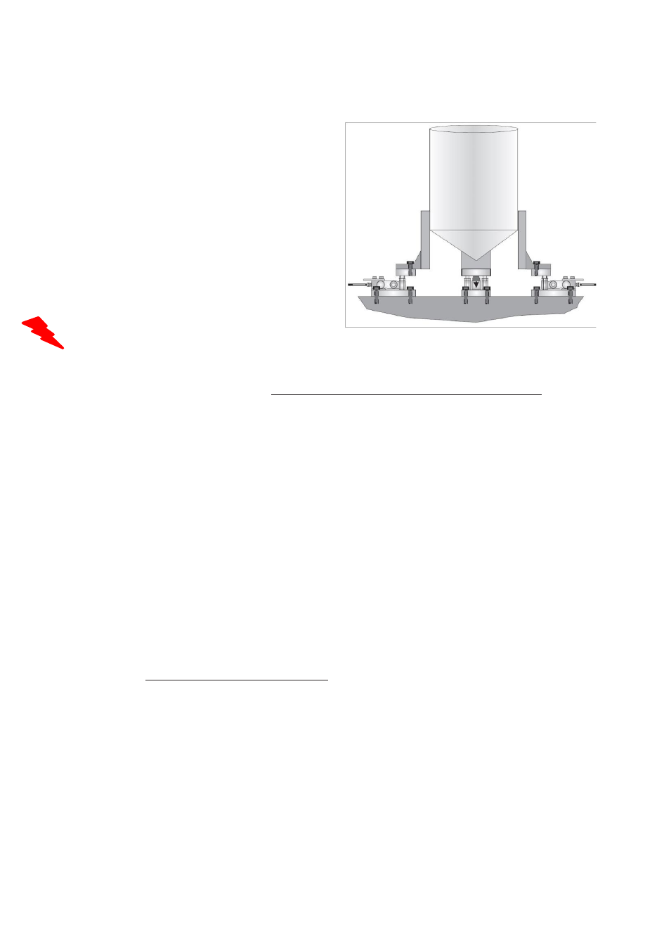
3 Leg tank or silo fitted with 3 load cells of 1000kg;
load cell signal @ 1000kg = 2 mV/V.
Dead load of tank / silo is 600kg.
Live range is 1 500kg, step size is 0.5kg.
It is assumed that the load cell system is connected
to the DAD 141.1 and the power is on. The maximum
and minimum display values, display increment size
and decimal point position should be defined prior to
carrying out the calibration (See chapter 7.5 menu 3).
For this example the display maximum is defined as
1600.0kg, the display minimum is -200.0kg, the
Display step size is 0.5kg.
Remember that all parameters of the menues 1.1 - 1.3, 2.1 - 2.3 and 3.1 - 3.3 can only be accessed or
changed after remove the jumper on the seal switch pins (28).
a A scale calibration by using weight(s) can only be performed in the scale sta
tus ‘no motion‘. This requires
in any case to check the settings of menu 4.
Recommendations for setup as follows:
-
Menu 4.1: set cut off frequency to 4.1.7 = 0.5Hz
-
Menu 4.2: choose IIR filter
-
Menu 4.4.1: set no motion range e.g. to 2, which means for this example 0.2kg
-
Menu 4.4.2: set no motion time to 1000, which means 1000ms or 1s
In case of outdoor application or indoor with a lot of mechanical noise from the floor/ground, may be you
have to change
the ‘no motion‘ settings.
b Go to Menu 3.2 (display step size) by using the UP/DOWN and ZERO keys. The display shows the
actual step size, e.g. 1. Now you can change step size by using the UP/DOWN keys and set to 5.
Press the ZERO key to store & leave menu point. This procedure defines the step size to 5, which leads
with the setup of decimal point to 0.5kg steps.
c Go to Menu 3.3 (decimal point position) by using the UP/DOWN and ZERO keys. The display shows the
actual decimal point, e.g. 0.0. Now you could change decimal point position by using the UP/DOWN
keys, but in this example we keep the setup. Press the ZERO key to store & leave menu point.
This procedure defines the decimal point position to 0.0, which leads to weight readings of e.g. 498.5kg.
d Go to Menu 1.2 by using the UP/DOWN and ZERO keys. The display shows the actual mV/V value,
e.g. 0.4107. Make sure that the tank/silo is empty or at the point where you want the display to read zero.
Press the ZERO key to set the display to read 0000.0kg. This procedure defines the actual zero calibration
point. Leave this menu point with ZERO key.
e Go to Menu 2.1 by using the UP/DOWN and ZERO keys. Set the display to read the span value of the
calibration weight(s) applied. For this example, if the calibration applied load is 750kg, set the display to
read 750.0. By using the UP/DOWN and TARE keys you have to setup each number of the 6 digit display
to 00750.0. Press now ZERO key for storage. This procedure defines the span calibration value.
Leave this menu point with ZERO key.
f Go to Menu 2.2. by using the UP/DOWN and ZERO keys. Apply the calibration weight(s) to the weighing
system. The display will show the actual input signal in mV/V, e.g. 0.9087. Press the ZERO key to set the
display to read 750.0kg. The gravimetric calibration is done.
Leave this menu point with ZERO key.