1. operating controls, 1 operating controls, Operation – Kenwood TH-27A User Manual
Page 8
Attention! The text in this document has been recognized automatically. To view the original document, you can use the "Original mode".
4. OPERATION
4-1. OPERATING CONTROLS
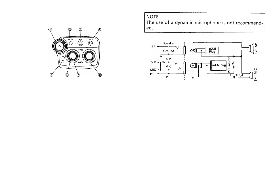
0 Antenna connector
Connect the antenna that is supplied to this connector.
Twist to lock,
d) DC IN terminal
This terminal is used for an external power supply. Input
voltage is 1 3.8 VDC nominal. The center is the + side
and the sleeve is the — side.
NOTE
You should turn the power switch OFF when connect
ing a power source to this terminal. Pay close atten
tion to polarity.
Use the KENWOOD PG-2W or PG-3F optional cable for
connection.
0 MIC jack
This jack is used for connection of an external micro
phone. The use of an electret type microphone is
recommended. Input impedance is 2kfl and the DC
voltage on this terminal is Approx. 4 V (MAX 3.5 mA).
8
0 SP jack
This jack is used to connect an external speaker or
earphone. The recommended impedance is 8il.
0 ON AIR indicator
On whenever the transceiver is in the transmit mode.
(D VOL control
Rotating the control further clockwise will increase the
volume.
0 SQL(Squelch) control
This control is used to select the desired Squelch
threshold level.
0 Tuning control
This control is used to select the desired transmitter
/receiver frequency, MHz step. Memory Channel, Fre
quency Step, Tone Frequency, Scan Direction, etc.