3 accessories, 4 installation instructions, 1 installation mounting bracket – Kenwood TM-441A User Manual
Page 7: Accessories, Installation instructions, 3accessories, 4installation instructions
Attention! The text in this document has been recognized automatically. To view the original document, you can use the "Original mode".
3
ACCESSORIES
Unpack your new transceiver carefully, and examine it
for visible damage If the equipment has been
damaged
in
shipment,
notify
the
transportation
company immediately. Save the boxes and packing
material for future shipping.
The following accessories should be included in the box
with the transceiver.
DTMF Microphone
(U.S.A. CANADA only)................. T91-0380-X5 1 ea.
or
Dynamic Microphone
(GENERAL market only) ............. T91-0379-X5 1 ea.
or
Dynamic Microphone
(EUROPE market only) ............... T91-0382-X5 1 ea.
Microphone Hook
(U.S.A. CANADA only) ................ J20-0319-24 1 ea.
Mobile Mounting Kit
Bracket ............................. J29-0436-03 1 ea.
Screw set .......................... N99-0331-05 1 ea.
Self tapping Screw
(U.S.A. CANADA only) ...
N46-3010-46 2 ea.
Hex wrench ................................. WOl-0414-041 ea.
Stacking plate
(TM-441A/441E/541A/541E)..
J21-4147-14 2 ea.
DC power Cable .......................... E30-2111-05 1 ea.
Fuse (TM-241A/241E: 15A)..
F05-1531-05 1 ea.
(TM-441A/441E: lOA)..
F05-1031-05 1 ea.
(TM-541A/541E: 8A) ...
F05-8021-05 1 ea.
Instruction Manual ....................... B62-0031-XX 1 copy
Warranty Card ..................................................... 1 ea.
(U.S.A., CANADA , EUROPE market s only)
4
INSTALLATION INSTRUCTIONS
4-1 INSTALLATION
Mounting Bracket
When installing the transceiver in a vehicle consider the
ease of operation and safety when selecting the
location for the mounting bracket.
1. Install the bracket using the supplied flat washers
and self tapping screws ( 4 pcs.each).
2. Attach the transceiver loosely using the 4 SEMS
screws.
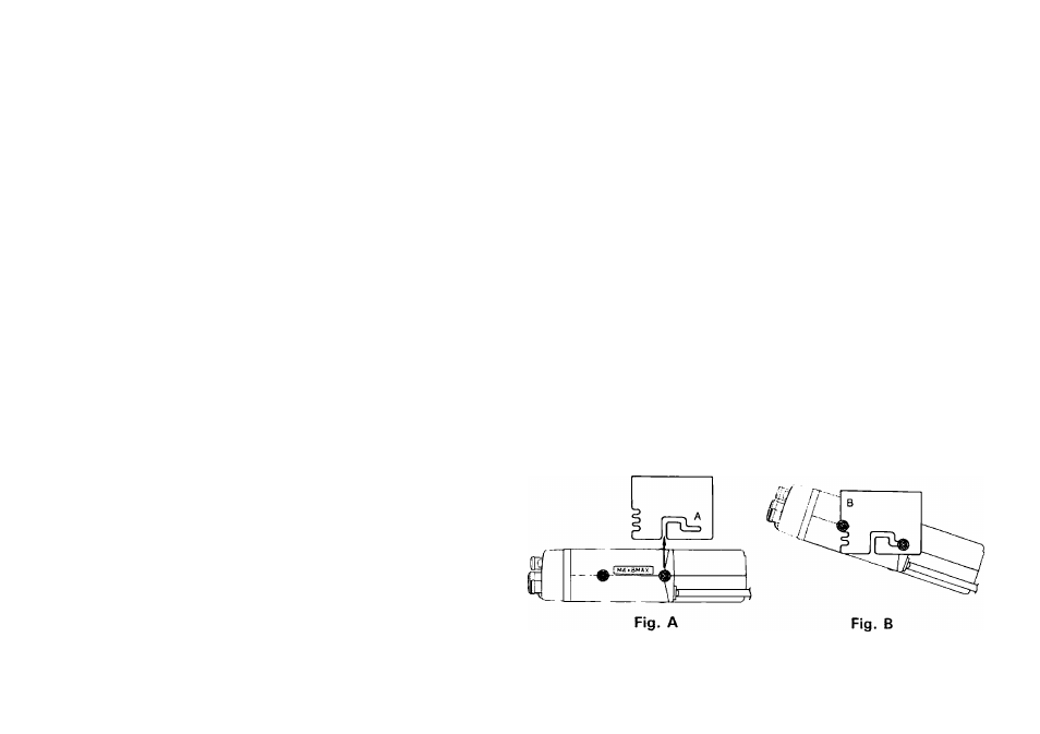
3. Align the grooves in the bracket with the
transceiver’s screws ( Fig. A) and slide the transceiver
to the rear.
4. Adjust the viewing angle in the bracket to the
desired position ( Fig. B).
5. Hold the transceiver in place and tighten the 4 SEMS
screws using the supplied wrench.