Carl Goldberg GPMA1968 Tiger 60 ARF User Manual
Page 9
9
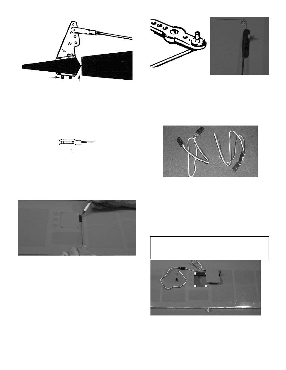
3.
Position the control horn so that the snap link
holes are right next to the hinge line, as
shown.
4.
Using a 5/64" drill bit, make a pilot hole in
each screw location.
Mount the control horn with the 2-56 x 3/4"
screws.
5.
Thread the 2mm x 155mm rod onto the snap
link. Make sure the rod shows in the center of
the snap link.
Place the snap link in the second hole from
the top on the control horn. Slide the silicone
keeper in place
6.
Make sure the aileron is in neutral (level)
position, mark where the wire meets the hole
on the servo arm.
Remove the wire and cut it about 1/2"
beyond the mark.
Make a 90º bend (or a "z" bend, if preferred)
in the wire and insert the wire in the servo
arm.
Secure the wire with a snap nut and then put
a drop of ZAP CAt™ on the snap nut to
make sure it stays in place.
PLACE CONTROL HORN AT HINGE LINE
2-56 X 3/4" SCREWS
SNAP LINK
CONTROL
HORN
SERVO EXTENSION INSTALLATION
1.
Gather the following items:
(2) 6" Extension wires
(1) Wing
2.
Remove the servo door and plug one 6"
extension wire into the servo.
If the extension is not long enough to reach
to the center of the wing, add an additional
extension to each extension wire for correct
length.
IMPORTANT! To ensure that any connections located
inside the wing will not come loose, either when the
wires are pulled, or during flying, always tape them
securely together with electrical tape.
3.
Making sure to use the correct servo for the
opening, attach the servo wire to the 6"
extension and securely tape the connection.
Push the extension wire into the tube in the
wing until it comes out hole near the center
of the wing.