Carl Goldberg GPMA1968 Tiger 60 ARF User Manual
Page 23
23
RADIO SWITCH INSTALLATION
1.
Collect the following items:
(1) Radio switch
(1) Switch mount
(1) Switch mount bolt
(1) Switch cap
(1) Switch push-pull
(2) #2 washer
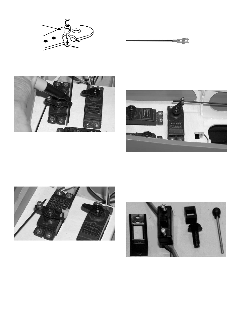
10.
With the servo arm NOT ATTACHED to the
servo, mount a pushrod connector to the
middle hole on the servo arm.
Insert the nosegear pushrod into the pushrod
connector on the rudder servo arm.
Place the servo arm onto the rudder servo,
with the rudder pushrod passing over the top
of the arm.
11.
Making sure the arm is perpendicular to the
centerline of the servo, mark where the wire
crosses over the outer hole in the servo arm.
Make a 90º upward bend at the mark in the
wire.
12.
Place a snap-r-keeper onto the top of the
rudder wire and push it into place.
13.
Remount the servo arm on the servo, again
positioned so it is perpendicular to the servo
centerline.
Making sure that the rudder is in the neutral
position and the nose gear is pointing straight
ahead, tighten the setscrew on top of the
pushrod connector.
14.
On the 18" wire threaded on one end, install
a snap link.and silicone keeper.
15.
Insert the wire into the tube that is in front of
the firewall and right behind the engine throt-
tle arm.
Slide the wire into the tube until the snap link
can be placed onto the engine throttle arm.
Remove the servo arm and insert the rudder
pushrod into the outer hole in servo arm
while keeping the nosegear pushrod in the
pushrod connector.
PUSHROD CONNECTOR
SNAP NUT
16.
Install a pushrod connector on the third servo
arm. Insert the throttle wire into the pushrod
connector and place the arm on the throttle
servo.
The throttle servo movement will be adjusted
after the receiver and battery pack are
installed.
DuBro switch mount Part # 203 not included in kit.