Carl Goldberg GPMA1968 Tiger 60 ARF User Manual
Page 25
25
MAIN GEAR & WHEEL INSTALLATION
BALANCING THE MODEL
Using a scissors, cut the backing along the
bubble, removing a strip of backing about 1"
wide.
Carefully position the decal on the model
and, working from the center, rub the decal
down while peeling back the remainder of the
backing.
Note: Do not remove the decal backing from the
dashboard. Glue the decal with the backing
on to the dashboard. You can also place a
white backing on the dashboard before you
peel and apply the decal.
1.
Collect the following items:
(2) Landing gear wire
(8) #2 x 5/16"screw
(4) Landing gear strap
(3) 2-1/2" wheel
(3) 5/32 wheel collar
(3) 6-32 x 1/8" Allen head set screw
(3) 5/32 eyelet
(1) .050 Allen wrench
4.
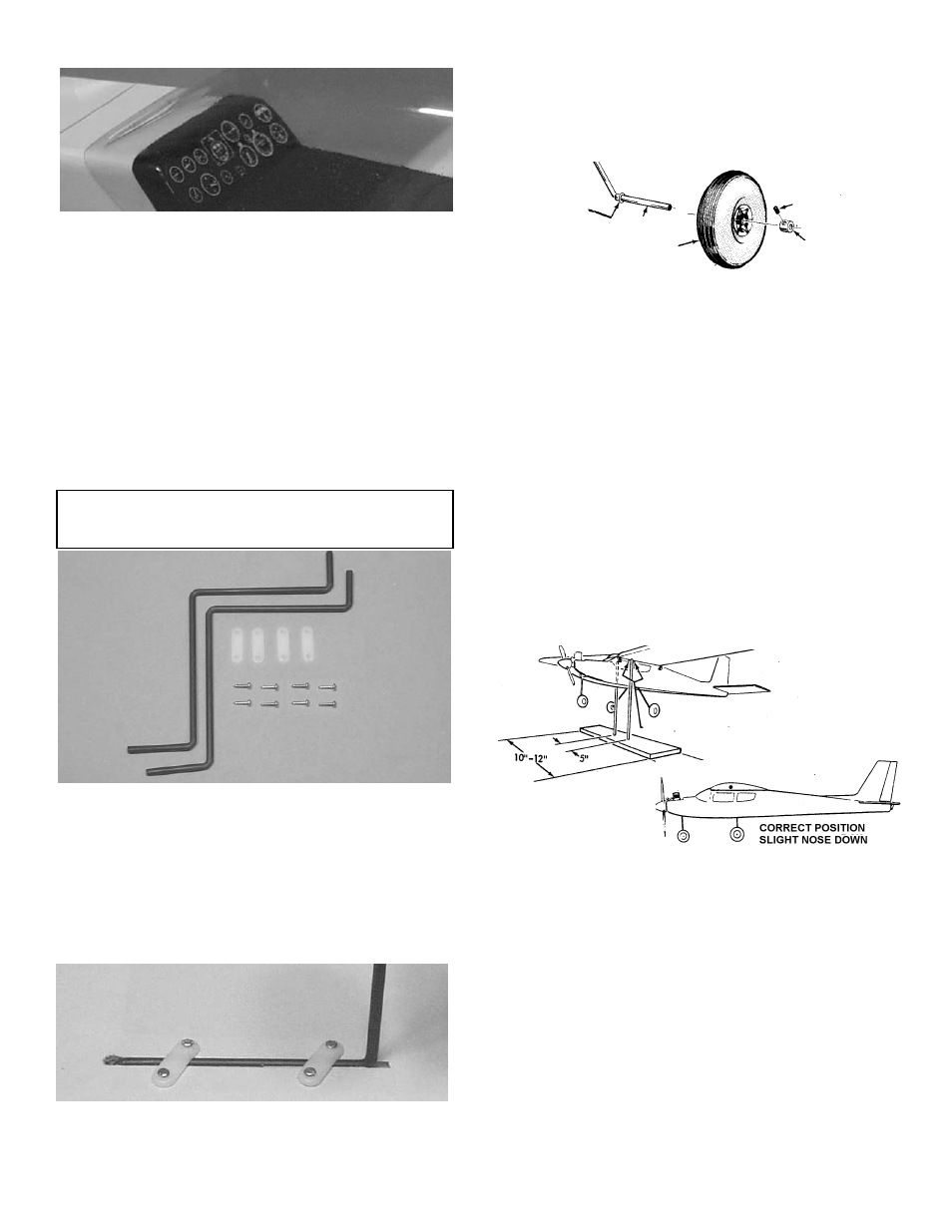
Install the wheels on the axles, as shown.
The eyelet goes on first, followed by the
wheel, the wheel collar, and the set screw.
Glue the eyelet in place with a drop of ZAP
CA™.
5.
At this time, also install the nosegear wheel.
2.
Locate the landing gear slots in the bottom of
the wing and remove the covering material.
NOTE: If you desire the taildragger configuration,
go the the Landing Gear Installation in the
Taildragger Option section.
EYELET
AXLE
WHEEL
SET SCREW
WHEEL COLLAR
Insert the shorter end of the gear into the
hole in the bottom of the slot, so that it points
toward the center of the wing.
3.
Use two nylon straps and four screws on
each side to secure the wire gear.
IMPORTANT: NEVER NEGLECT THIS STEP WITH
ANY AIRPLANE. If you try to fly a plane with the
balance point behind the recommended range, you
run the risk of having an unstable aircraft and the
strong likelihood of a crash. TAKE THE TIME TO
PROPERLY BALANCE YOUR MODEL!
To determine the Center of Gravity, measure back
on the fuselage 3-7/8" from the leading edge of
the wing. The C.G. range for this aircraft is 3-3/4
to 4-3/4".
Place the fully assembled aircraft on a model bal-
ancing stand, as shown above. You can make this
simple set-up with a couple of ¼" dowels with round-
ed tops, spaced 5" apart. Alternatively, lift the model
under the wing near the fuse by your finger tips. (You
may wish to get help from a friend if using the latter
method.)
Referring to the recommended balance
range for your model, move the position of the plane on
the balance stand until the model is level or the nose
slightly down.
If the is tail heavy, shift the R/C equip-
ment away from the heavy end of the model and
recheck until the model will balance within the
acceptable range. If shifting the R/C gear still does-
n't balance the model, add weight to the far end of
the nose or tail, respectively, until the model is cor-
rectly balanced. The least weight is needed when
added as far back or forward as possible. Fasten
the weight permanently in place.