Carl Goldberg GPMA1968 Tiger 60 ARF User Manual
Page 10
10
5.
Repeat these steps for the other half of the
wing, so that both servo extensions are exit-
ing the holes in the center of the wing.
WING INSTALLATION ON FUSELAGE
3.
Working with the fuselage upside down,
insert a 6-32 blind nut into each hole in the
wing mounting blocks, with the teeth pointing
upward into the blocks.
Temporarily insert a 6-32 x 1" screw into
each hole on the other side of the mounting
block and draw the blind nut teeth down into
the wood.
When the blind nuts are firmly seated in the
wing mount blocks, remove the screws.
FUSE SHOWN UPSIDE DOWN
SCREW
WING
BLIND NUT
4.
Gently prodding the covering, locate the hole
next to the center of the of the wing, close to
the trailing edge.
Carefully remove the covering OVER THE
HOLE in the wing on both the top and the
bottom.
Do the same to the other wing panel.
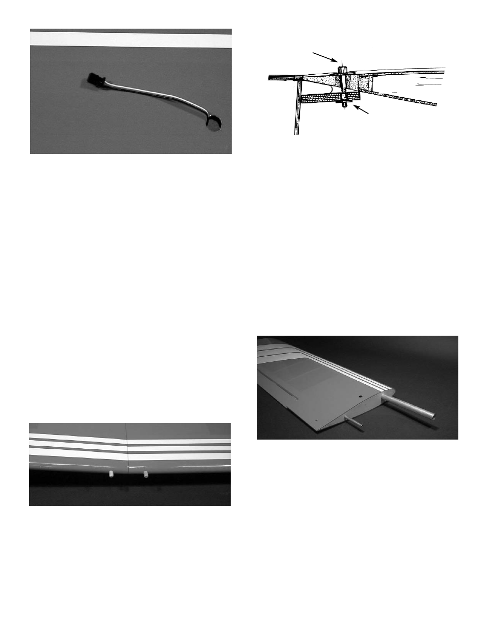
5.
Insert the large aluminum tube into one wing
half and push the tube into the wing until it
stops. Then insert the small aluminum tube
into the small hole till it stops. Then slide the
wing halves together.
4.
Grasping the extension in the hole, SLOWLY
pull until the end of the 6" extension comes
out of the hole.
Tape the extension securely to the wing, so
that it will not slide back in while you are
working.
Screw the servo door into the wing.
NOTE: If the covering on your wing has loosened in
transit, refer to the covering section of the
"INTRODUCTION" before continuing.
1.
Collect the following items:
(1) Right wing
(1) Left wing
(2) 5/16 x 1-1/2" dowel
(1) Large aluminum tube
(1) Small aluminum Tube
(2) 6-32 x 1-1/2 Socket Head bolt
(2) 6-32 Blind nut
(2) #6 x 3/4” washer
2.
Using ZAP ZPOXY™, mount the 5/16 x 1-
3/4” dowels into the holes in the leading edge
of the wing. Make sure to leave about 1/2” of
dowel sticking out of the front of the wing. You
may wish to slightly taper the exposed dowel
ends for ease of insertion into the fuse holes.