Carl Goldberg GPMA1968 Tiger 60 ARF User Manual
Page 15
15
3.
Place the center of the control horn on the
hinge line and mark the location of the screw
holes on the elevator.
Using a 5/64" drill bit, drill the holes through
the elevator.
Using two 2-56 x 3/4" screws, screw the con-
trol horn and the backplate tightly to the ele-
vator.
1.
Collect the following items:
(1) Rudder
(1) Elevator
(3) Jet hinge
(2) Control horn
(4) 2-56 x 3/4" machine screw
2.
Measuring from the fuselage side, make a
mark on the elevator hinge line 3/4" from the
fuse on the right side of the plane.
RUDDER & ELEVATOR CONTROL HORN
INSTALLATION
NOTE: If you wish to fly your Tiger in the tail-dragger
configuration, do not install the rudder con-
trol horn according to the directions in this
section. Refer to the Tail-Dragger Option
section toward the end of the book.
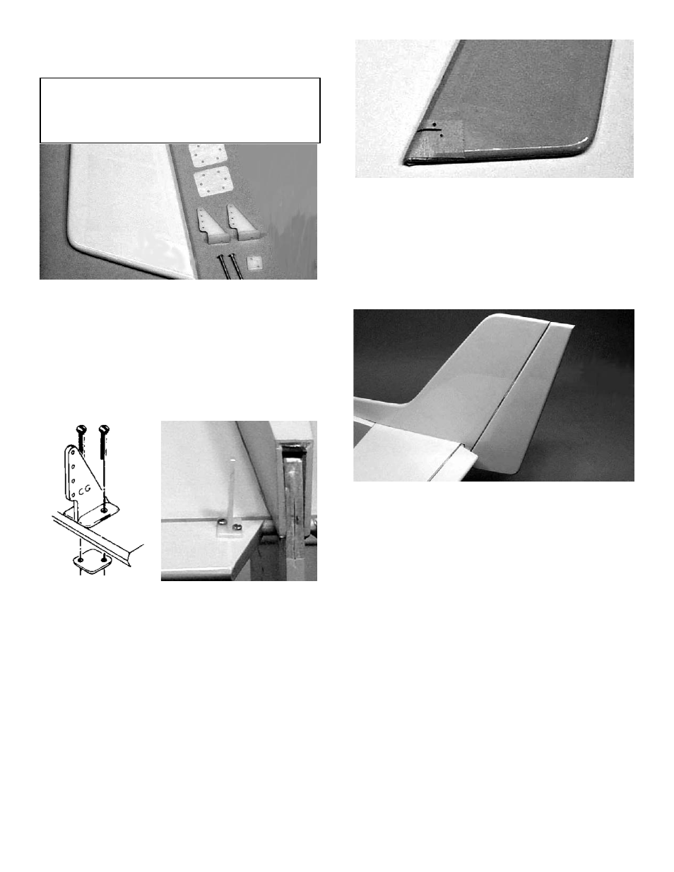
4.
With the rudder sitting on the table top, as
shown, mark 5/8" up from the bottom of the
rudder on the left side of the plane.
As with the elevator, position the control horn
and mark the holes.
Drill the holes for the control horn.
Again using two machine screws, secure the
control horn to the rudder.
5.
Using the three Jet™ hinges, mount the rud-
der to the fin, just as was done for the eleva-
tor and the ailerons.