Carl Goldberg GPMA1968 Tiger 60 ARF User Manual
Page 22
22
Insert the wire though the outer servo arm
hole and install a snap-r-keeper on the wire.
9.
Insert the other pushrod into the fuselage
and exit through the guide on the left side.
Again remove the covering over the exit hole.
As with the elevator servo pushrod, thread a
snap link onto the end of the wire and then
attach the snap link to the rudder control
horn. Be sure to slide the silicone rubber
keeper onto the snap link
With the rudder in neutral position, tape the
rudder to the fin.
8.
Place the servo arm onto the elevator servo,
so that the arm is perpendicular to the cen-
terline of the servo and the elevator pushrod
wire passes over the top of the servo arm.
Mark where the wire crosses over the outer
hole in the servo arm.
Using a long-nose pliers, make a 90º bend
upward at the mark.
7.
Take the two pushrods you made and bend
the end with the threaded rod out at a 10
degree angle. Avoid sharp bends in the
pushrod, we only want it to turn our slightly.
Route the pushrod into the fuselage and out
the exit on the right side of the plane.
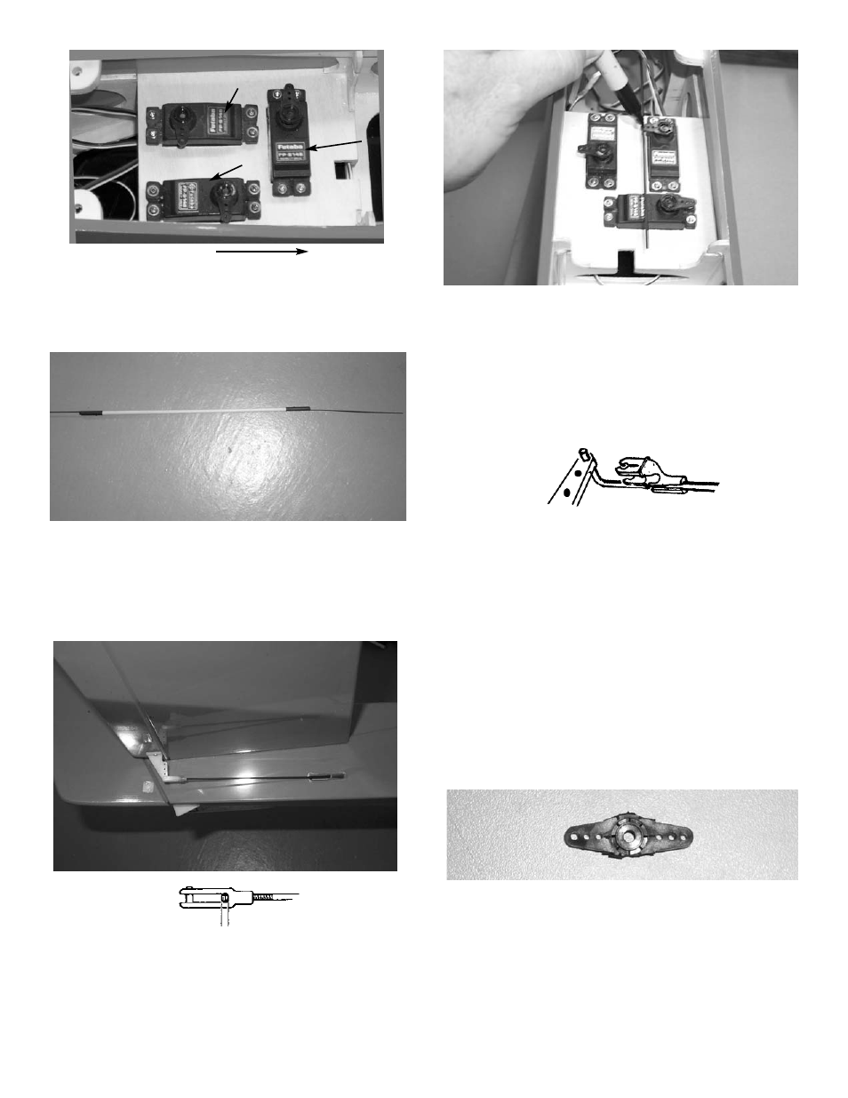
6.
Using the screws that came with the radio,
install the three servos, as shown. The ele-
vator servo goes on the right side of the
plane.
Front of model
Throttle servo
Elevator servo
rudder servo
Thread a snap link onto the threaded end of the
wire exiting the rear of the model, as shown
above.Slide the silicone keeper in place.
Attach the snap link to the elevator control
horn. Then tape the elevator so that it is in
the neutral (level) position.
For the rudder you will need a servo arm
modified to look like the one above. Cut
off the extra arms so you have two arm
directly across from each other.