Carl Goldberg GPMA1968 Tiger 60 ARF User Manual
Page 24
24
RECEIVER AND BATTERY INSTALLATION
2.
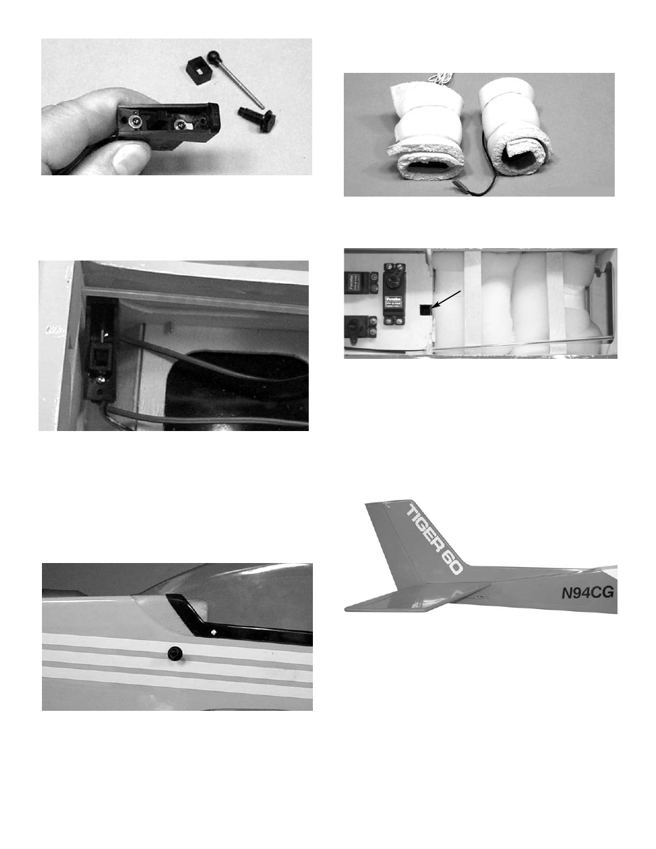
If your radio has a switch cover, remove both
the screw and the cover from the top of the
switch.
Using the screw just removed, as well as the
#2 washer, assemble the switch mount as
shown.
3.
The switch mount has one slotted hole on
one side and two holes on the other side.
Mount the switch so that it will move back
and forth. It will be possible to feel and hear
the click.
Locate the switch on the left side of the fuse,
about 3-3/16" up from the bottom of the fuse
and 9-5/16" from the nose of the fuse.
4.
Drill a 1/4" hole and insert the switch mount
bolt through the hole.
Screw it into the switch mount. Then, insert
the push-pull and screw it into the switch
cap.
1.
Insert the Y-harness into the the aileron
plug in the receiver and then wrap both the
receiver and the battery in the 1/2" foam.
2.
Place the receiver just behind the radio
switch and the battery in front of the servos.
Plug in all of the servos, keeping both the
aileron and the charge cord accessible.
Glue the two wood pieces (from scrap) to the
fuse sides, as shown, to keep the receiver
and battery from shifting.
DECAL APPLICATION
1.
Using glass cleaner and a soft cloth, clean
the model surface thoroughly before apply-
ing decals.
2.
Cut the decal sheets apart in sections, as
needed.
Fold the decal in half, front to rear. Open at
the fold and place the decal on a flat surface.
The protective backing will bubble away from
the decal at the fold.
Switch can be mounted
in servo tray if DuBro
switch mount is not used.