Carl Goldberg GPMA1968 Tiger 60 ARF User Manual
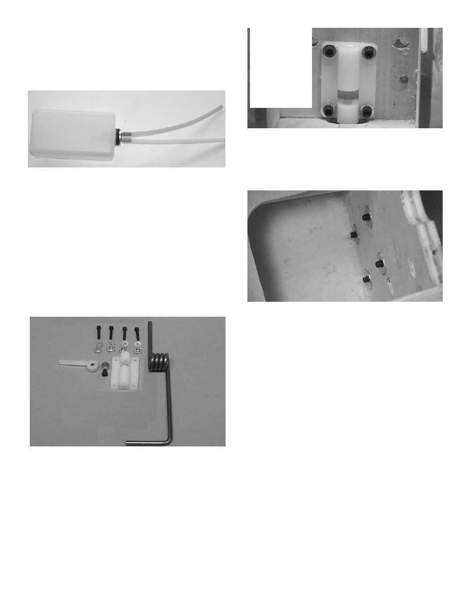
Page 17
17
6.
Attach the two pieces of 5mm tubing to
the two tank outlets. They are different
colors so you can tell which is the vent
and which is the fuel pickup after the tank
is installed. Make a note of which color
you attatch to which tube. The short
brass with the clunk is the fuel pickup
and must go to the carbeuator. The long
brass tube is the vent and should go to
the pressure outlet on the muffler.
Set tank aside till ready to install.
5.
Install the assembly into the tank so the
vent tube is turned up to the top of the
tank and is positioned on the right side of
the tank. Tighten the screw to expand the
rubber cap. Don’t overtighten or you
could split the tank.
3.
Place the 4-40 blind nuts, with the teeth
pointed toward the firewall, on the ends of the
screws. Tighten until the blind nut teeth are
firmly seated into the wood.
2.
Referring to the above photo, and using the
allen wrench supplied with this kit, screw the
nose gear block to the firewall with the 4-40 x
1/2" screws and the #4 washers. Screw the
bolts part way until the ends are just coming
through the back side of the firewall.
1.
Gather the following items:
(4) 4-40 x 1/2" socket head screw
(4) #4 washer
(4) 4-40 blind nut
(1) Nylon nosegear block
(1) Nose Gear Wire
(1) 5/32" wheel collar
(1) Nylon steering arm
(1) 6-32 x 3/16" socket head screw
(1) 1.5mm x 18” wire
NOSE GEAR INSTALLATION
Note: This
block has
changed.
Mount using
the top holes
and drill new
bottom holes.