Figure 6.10, Grounding terminal location, Figure 6.11 – AERCO KC Series Equipped with C-More version 3.04 User Manual
Page 55: Burner disassembly diagram, Maintenance
MAINTENANCE
6-8
5. Disconnect the flame detector and ignition cable wires from the flame detector and ignitor contactor.
Remove the flame detector and ignitor as per paragraphs 6.2, and 6.3.
6. Remove the grounding terminal from the burner by loosening the upper screw and sliding the
connector from the grounding rod, (See Fig. 6.10).
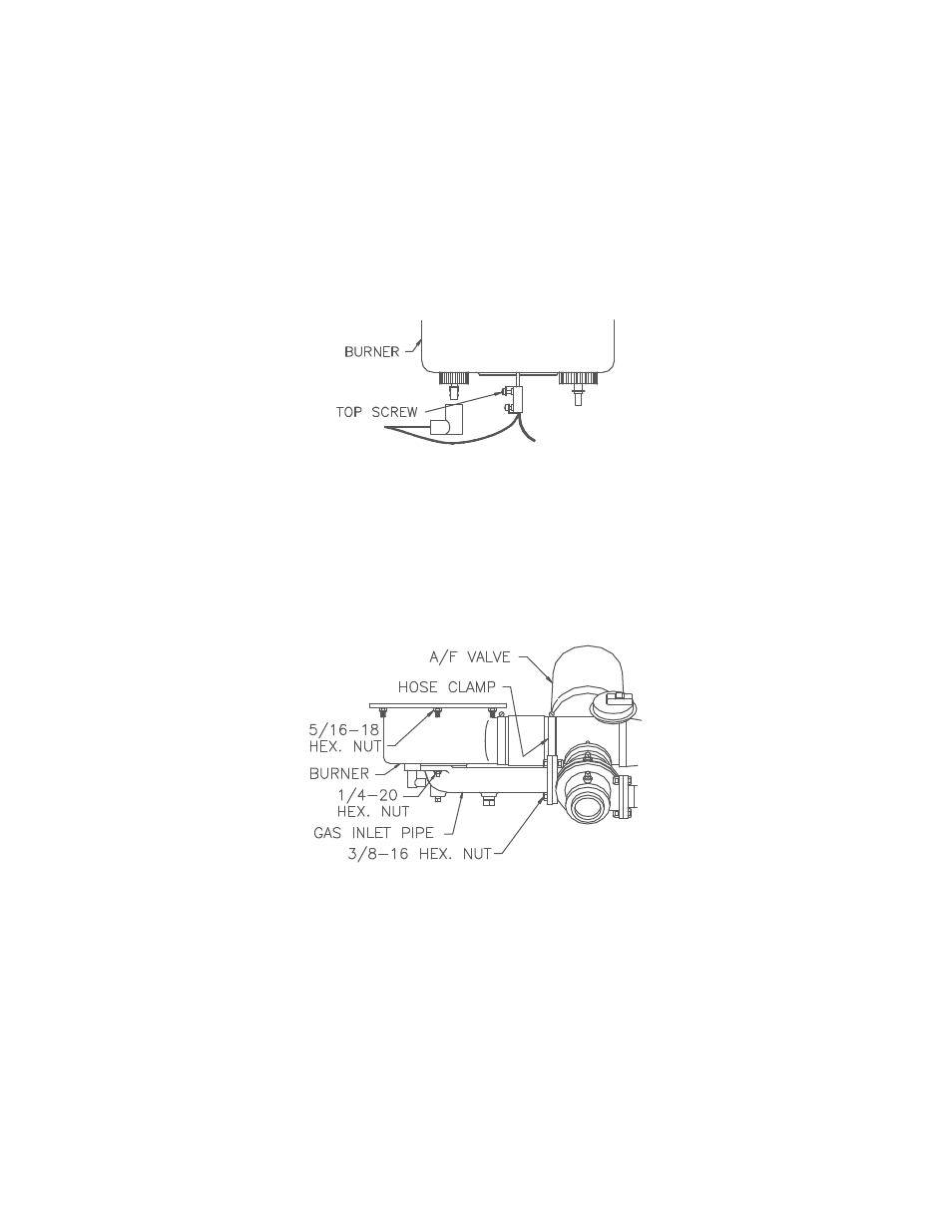
7. Using a 7/16” socket or open end wrench, remove the four 1/4”-20 nuts on the gas inlet pipe flange at
the burner, (See Fig. 6.11).
8. Using two 9/16” wrenches, remove the 3/8"-16 hex nuts and bolts on the gas inlet pipe flange at the
air/fuel valve, (see Fig. 6.11).
Figure 6.10
Grounding Terminal Location
9. Loosen the hose clamp at the air/fuel valve outlet and slide the clamp back towards the burner, (see
Fig. 6.11).
10. Using a 1/2” socket wrench remove six 5/16-18 hex nuts supporting the burner, (see Fig. 6.11).
Figure 6.11
Burner Disassembly Diagram
11. Lower the burner while sliding the air hose off the air/fuel valve. Remove the burner through the rear
of the unit.
12. Disconnect the exhaust temperature sensor by unscrewing it from the exhaust manifold, (See Fig.
6.12).