2 installing the supply gas manometer, Figure 4.1, 1/4” gas plug location – AERCO KC Series Equipped with C-More version 3.04 User Manual
Page 32: 3 preparing the flue vent probe hole, Figure 4.2, Analyzer probe hole location, Initial start-up
INITIAL START-UP
4-2
*For propane fired units, an additional 8" W.C. manometer and 1/2" NPT to barbed fitting is needed.
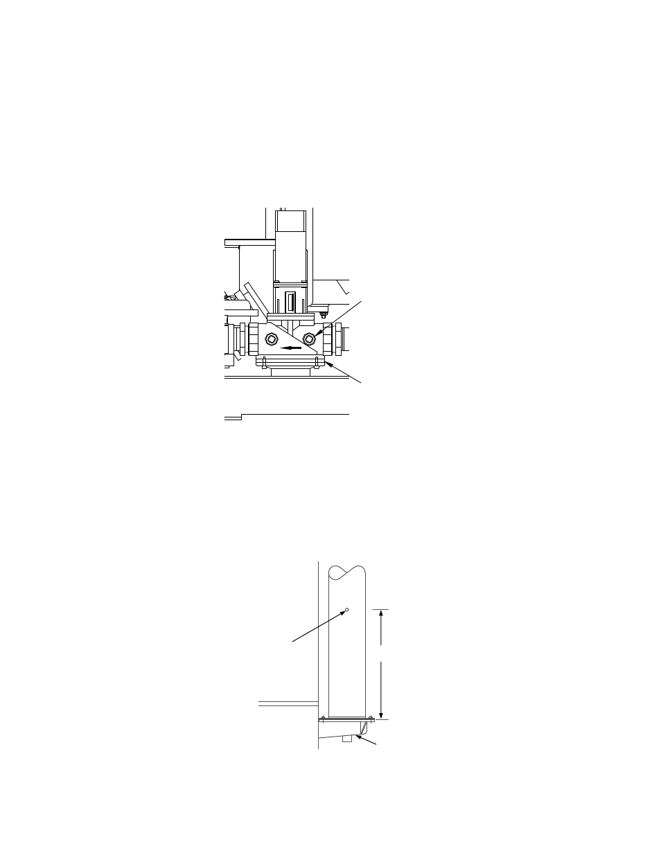
4.2.2 INSTALLING THE SUPPLY GAS MANOMETER
1. Close the main manual gas supply valve up stream of the unit.
2. Remove the 1/4" NPT pipe plug from the port on the inlet side of the safety shut off valve (see Figure
4.1).
3. Install a barbed fitting into the pipe plug tapping.
4. Attach one end of a length of plastic tubing to the barbed fitting and one end to the 16" W.C.
manometer.
SSOV
1/4" NPT PLUG
(INSTALL
MANOMETER
HERE)
Figure 4.1
1/4” Gas Plug Location
4.2.3 PREPARING THE FLUE VENT PROBE HOLE
1. If the unit has been installed using the recommended AL29-4C vent, there will be a 3/8” hole, 18” to
24” above the exhaust manifold. The outer vent section, that covers vent section connections must be
loosened and slid down to uncover the hole (see Fig. 4.2).
2. If equipped with one, adjust the stop on the combustion analyzer probe so that it extends into the flue
gas flow without hitting the opposite wall of the flue. Do not insert the probe at this time.
3/8" - 1/2"
HOLE FOR
COMBUSTION
ANALYZER
PROBE
EXHAUST
MANIFOLD
12" - 18"
Figure 4.2
Analyzer Probe Hole Location