10 fault relay, Figure 2.10 i/o box wiring, 7 flue gas vent installation – AERCO KC Series Equipped with C-More version 3.04 User Manual
Page 18: Installation, Danger
INSTALLATION
2-8
requires time to close (make), a time delay (Aux
Start On Dly) that holds the start sequence of the
unit long enough for a proving switch to make
(close) can be programmed. Should the proving
switch not prove within the programmed time
frame, the unit will shut down. The Aux Start On
Dly can be programmed from 0 to 120 seconds.
This option is locate in the Configuration Menu
(Section 3).
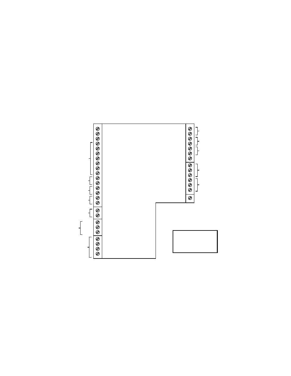
2.6.10 FAULT RELAY
The fault relay is a single pole double throw
(SPDT) relay having a normally open and
normally closed set of relay contacts that are
rated for 5 amps at 120 VAC and 5 amps at 30
VDC. The relay energizes when any fault
condition occurs and remains energized until the
fault is cleared and the
CLEAR button is
depressed. The fault relay connections are
shown in Figure 2.10.
2.6.11 AUXILIARY RELAY CONTACTS
Each unit is equipped with a single pole double
throw (SPDT) relay that is energized when there
is a demand for heat and de-energized after the
demand for heat is satisfied. The relay is
provided for the control of auxiliary equipment,
such as pumps and louvers, or can be used as a
unit status indictor (firing or not firing). Its
contacts are rated for 120 VAC @ 5 amps.
Refer to Figure 2.10 to locate the AUX RELAY
terminals for wiring connections.
mA OUT
RS-485
COMM.
+
-
+
-
ANALOG IN
SENSOR COMMON
OUTDOOR SENSOR IN
REMOTE INTL'K IN
B.M.S. (PWM) IN
SHIELD
+
-
+
-
AUX SENSOR IN
NOT USED
EXHAUST SWITCH IN
DELAYED INTL'K IN
FAULT RELAY
120 VAC, 5A, RES
AUX RELAY
120 VAC, 5A, RES
G
RELAY CONTACTS:
120 VAC, 30 VDC
5 AMPS RESISTIVE
DANGER
120 VAC USED
IN THIS BOX
NOT USED
NOT USED
NC
COM
NO
NC
COM
NO
NOT USED
Figure 2.10 I/O Box Wiring
2.7 FLUE GAS VENT INSTALLATION
AERCO Gas Fired Venting and Combustion Air
Guide, GF-1050, must be consulted before any
flue or combustion air venting is designed or
installed. Suitable, U/L approved, positive
pressure, watertight vent materials MUST be
used for safety and UL certification. Because
the unit is capable of discharging low
temperature exhaust gases, the flue must be
pitched back towards the unit a minimum of 1/4"
per foot to avoid any condensate pooling and to
allow for proper drainage.
While there is a positive flue pressure during
operation, the combined pressure drop of vent
and combustion air systems must not exceed
140 equivalent feet of 0.81” W.C. Fittings as
well as pipe lengths must be calculated as part
of the equivalent length. For a natural draft
installation the draft must not exceed - 0.25”
W.C. These factors must be planned into the
vent installation. If the maximum allowable
equivalent lengths of piping are exceeded, the
unit will not operate properly or reliably.