Figure 7.6, Air/fuel valve inlet hose clamp, Figure 7.7 – AERCO KC1000 Boiler equipped with Mod-Box Controller User Manual
Page 41: Figure 7.8, Manifold nut and bolt locations, Maintenance
MAINTENANCE
36
Figure 7.6
Air/Fuel Valve Inlet Hose Clamp
16. Using an 11/16” wrench, loosen the
compression fittings on the feedback tube
between the air/fuel valve and the differential
pressure regulator. Remove the feedback
tube (See Fig. 7.7).
17. Using two 9/16” wrenches remove the two
3/8-16 hex nuts and bolts holding the air/fuel
valve to the differential pressure regulator
(See Fig. 7.7).
18. Remove the air/fuel valve taking care not to
damage the flange “O”- ring.
19. Remove the flue venting from the exhaust
manifold.
Figure 7.7
Feedback Tube and Air/Fuel Valve to Differential
Regulator Bolts
20. To prevent damage to and for easier
handling of the exhaust manifold it will be
necessary to remove the exhaust manifold
insulation. Using a 7/16” wrench or socket,
remove the 3 bolts and fender washers
securing the insulation to the exhaust
manifold.
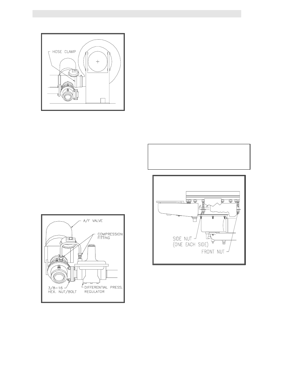
21. Loosen the three 1-1/16” nuts that hold the
manifold. Remove the two side nuts. DO
NOT REMOVE THE FRONT NUT (See Fig.
7.8).
22. Carefully pull the manifold down and back,
removing it through the back of the unit.
23. Inspect the manifold and exhaust tubes for
debris. Clean out any debris as necessary.
24. Inspect the combustion chamber and the
combustion chamber liner. Replace the liner
if any signs of cracking or warpage are
evident.
NOTE:
The combustion chamber liner should be
installed prior to reinstalling the exhaust
manifold
Figure 7.8
Manifold Nut and Bolt Locations
25. Replace the gasket between the manifold
and the combustion chamber (P/N GP-
122537). The use of Permatex or a similar
gasket adhesive is recommended. Replace
the gasket between the manifold and
tubesheet (P/N GP-18900). Do not use any
gasket adhesive; this gasket has an
adhesive backing
.