Pressure /temperature gauge installation, Pressure/temperature gauge installation, Condensate drain system location – AERCO KC1000 Boiler equipped with Mod-Box Controller User Manual
Page 10: Installation
INSTALLATION
5
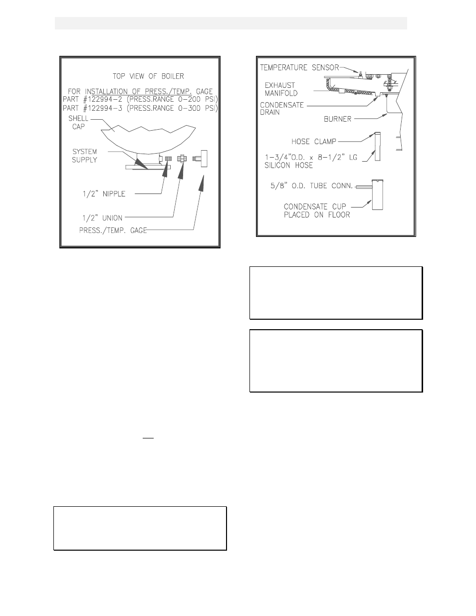
Figure 2.5b
Pressure/Temperature Gauge Installation
2.3.5 CONDENSATE PIPING
The KC Boiler is designed to condense and the
installation must have provisions for drainage to
a suitable waste. A 1-3/4” inch O.D. silicone
hose, supplied with the unit, directs condensate
from the exhaust manifold to a stainless steel
condensate cup. The condensate cup is shipped
loose and should be installed inside the unit
directly under the manifold’s condensate
drainage hole (see FIG. 2.6). A 5/8-inch O.D.
flexible polypropylene tubing (or suitable
equivalent) can be used to carry the condensate
by gravity to a nearby floor drain. If a floor drain
is not available, a condensate pump can be
used to remove the condensate to drain. The
maximum condensate flow rate is 5 GPH. The
condensate cup and line must be removable for
routine maintenance. Do not hard pipe.
2.4. GAS SUPPLY PIPING
The AERCO
Gas Fired Equipment Gas
Components and Supply Design Guide (GF-
1030) must be consulted before any gas piping
is designed or started.
WARNING!
DO NOT USE MATCHES, CANDLES,
FLAMES OR OTHER SOURCES OF
IGNITION TO CHECK FOR GAS LEAKS
.
Figure 2.6
Condensate Drain System Location
CAUTION!
Soaps used for gas pipe leak testing can be
corrosive to metals. Piping must be rinsed
thoroughly with clean water after leak
checks have been completed.
NOTE:
All gas piping must be arranged so that it
does not interfere with removal of any
cover, inhibit service or maintenance, or
prevent access between the Unit and walls,
or another unit.
The location of the 1-1/4" inlet gas connection is
on the right side of the unit as shown in Figure
2.7.
All pipe should be de-burred and internally
cleared of any scale or iron chips before
installation. No flexible connectors or non-
approved gas fittings should be installed. Piping
should be supported from floor or walls only and
must not be secured to the unit.
A suitable piping compound, approved for use
with gas, should be used sparingly. Any excess
must be wiped off to prevent clogging of
components.