Figure 3.9, Combustion safeguard status indicator led location, Figure 3.10 – AERCO KC1000 Boiler equipped with Mod-Box Controller User Manual
Page 20: Water level test and reset switch locations, Control panel operating procedures
CONTROL PANEL OPERATING PROCEDURES
15
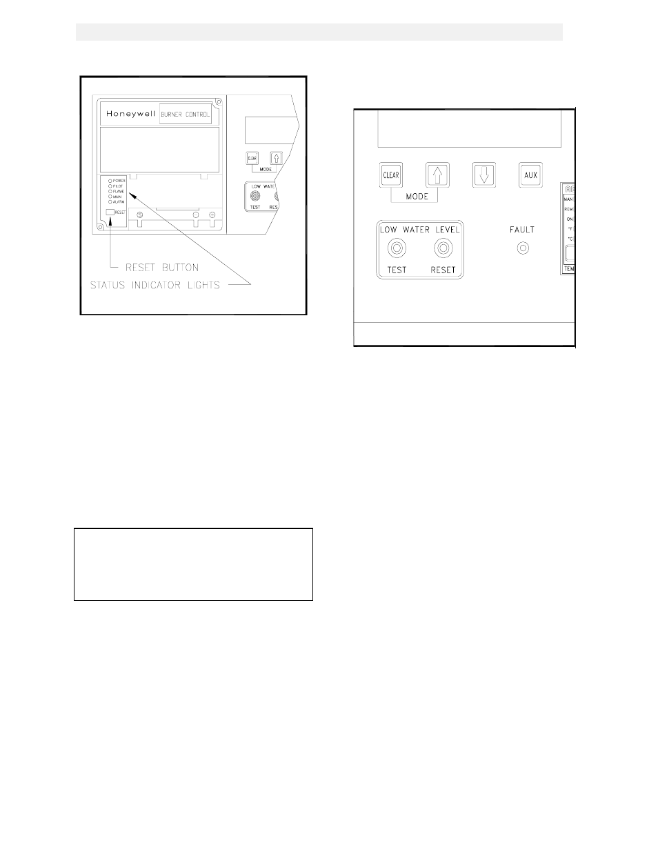
Figure 3.9
Combustion Safeguard Status Indicator LED
Location
3.7 WATER LEVEL TEST and RESET
SWITCHES
The water level switches are located on the left
side of the control box, see Fig. 3.10). When
depressed the TEST switch simulates a low
water level condition by breaking the connection
between the water level probe and the sensing
circuitry. To test the low water level circuitry,
depress the test switch for 3 seconds. The unit
should fault resulting in the red fault light blinking
and the LED display showing LOW WATER
LEVEL.
Note:
Only water level circuitry is tested during the
above test. To determine if the probe is
functioning properly, the water level must be
reduced below the level of the probe.
To reset the unit, depress the water level reset
switch, the annunciator clear button, and if
necessary, the reset button on the combustion
safeguard.
3.8 ON/OFF SWITCH
The ON/OFF switch is located on the right side
of the control panel above the temperature
controller (see Fig. 3.1). It is part of the start
string and must be in the ON position to enable
the unit to fire. When the switch is in the ON
position and illuminated, it is indicating that the
start limit string, consisting of water temperature,
gas pressure, water level, and the interlock is
satisfied, and that the alarm relay is not
activated. The unit at this point is in standby
mode and ready to run.
Figure 3.10
Water Level Test and Reset Switch Locations
3.9 STARTING SEQUENCE
When the unit is in the standby mode, and there
is a demand for hot water, the following will
occur:
1. Upon demand the temperature controller’s
ON status indicator will light.
2. The combustion safeguard’s PILOT LED
lights and the blower contactor energizes,
starting the blower.
3. The system next checks for proof of closure
from the safety shut-off valve, (see Fig.
3.11), and the air fuel valve rotates open
engaging the air /fuel valve open switch (see
Fig. 3.12).
4. The LCD display shows PURGE INTLK
OPEN until the above conditions are met.
Once met the LCD display will show LOW
AIR FLOW.
5. The blower proof switch closes, (See Fig.
3.13), and the LCD display will show
PURGING.
6. Closure of the blower proof switch signals
the combustion safeguard to begin its 7-
second purge cycle.