Figure 3.11, Proof of closure switch location, Figure 3.12 – AERCO KC1000 Boiler equipped with Mod-Box Controller User Manual
Page 21: Figure 3.13, Blower proof switch location, Figure 3.14, Control panel operating procedures
CONTROL PANEL OPERATING PROCEDURES
16
CONNECTOR
149
VALVE
SHUT-OFF
SAFETY
SWITCH
CLOSURE
PROOF OF
9A
148
145
146
147
FROM
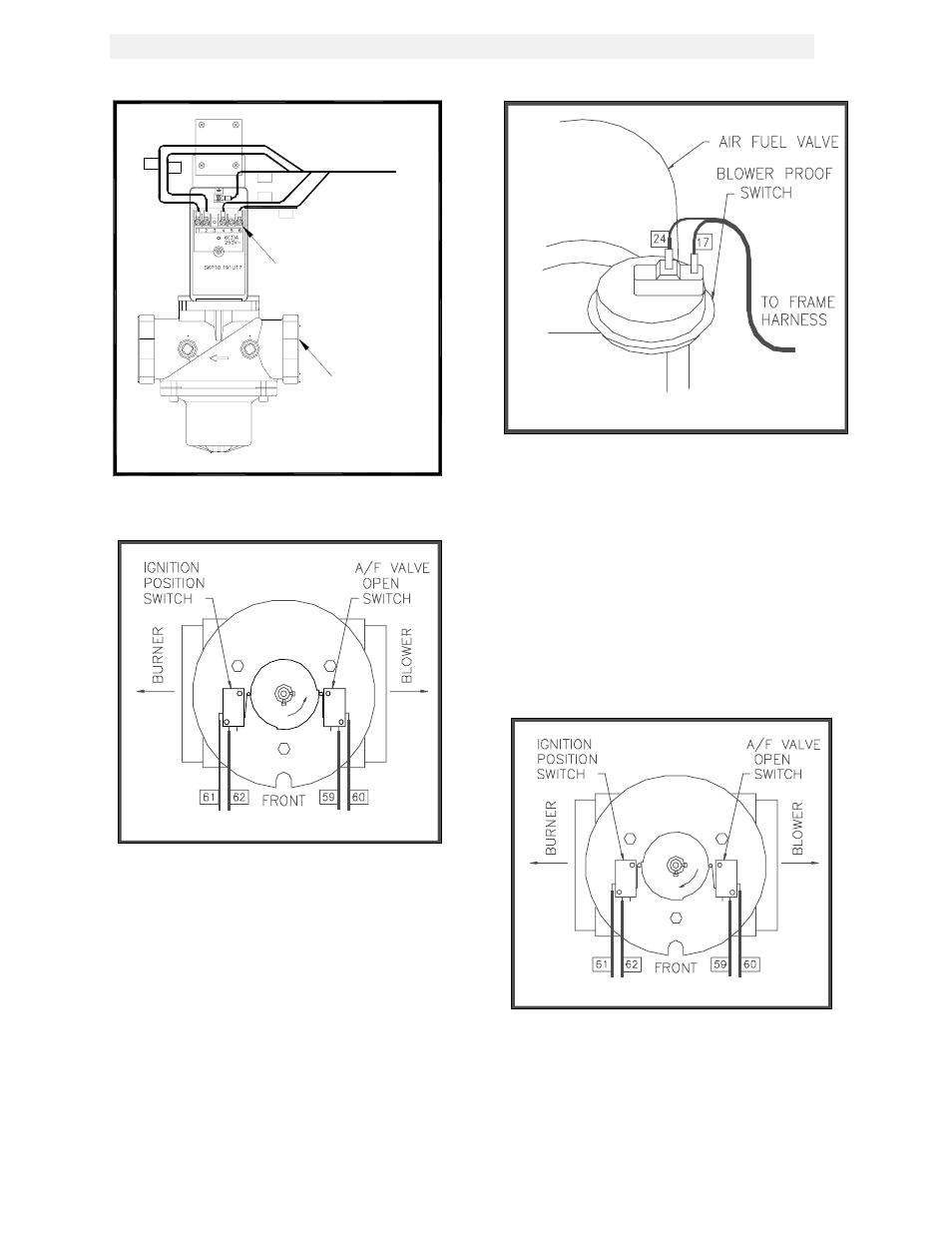
Figure 3.11
Proof of Closure Switch Location
Figure 3.12
Air/Fuel Valve Open and Engaging the Air/Fuel
Valve Open Microswitch
7. At the end of the purge cycle the combustion
safeguard initiates a 10 second trial for
ignition and the following simultaneously
occurs:
•
The LCD displays the message IGNITION
TRIAL.
•
The ignition transformer energizes.
•
The air/fuel valve rotates to its low fire
position. This engages the air-fuel valve
closed switch, energizing the safety shut-off
valve, (see Fig. 3.14).
Figure 3.13
Blower Proof Switch Location
8. Once the combustion safeguard detects
flame, its flame LED lights. Power is
removed from the ignition transformer and
the MAIN LED lights of the combustion
safeguard.
At this point, the annunciator will display FLAME
PROVEN. The unit, provided it is in the
automatic mode, is released to modulate and
will be controlled by the temperature control
system.
Figure 3.14
Air/Fuel Valve in Ignition Position, Engaging the
Ignition Microswitch