Section 6-safety device testing procedures, Figure 6.1, 1/8” pipe plug position for manometer installation – AERCO KC1000 Boiler equipped with Mod-Box Controller User Manual
Page 34: Safety device testing
SAFETY DEVICE TESTING
29
SECTION 6-SAFETY DEVICE TESTING PROCEDURES
6.1 TESTING OF SAFETY DEVICES
Periodic testing of all controls and safety devices
is required to insure that they are operating as
designed. Precautions must be taken while tests
are being performed to protect against bodily
injury and property damage.
Systematic and thorough testing of the operating
and safety controls should be performed on a
scheduled basis, or whenever a control
component has been serviced or replaced. All
testing must conform to local jurisdictions or
codes such as ASME CSD-1.
NOTE:
MANUAL and AUTO modes are required to
perform the following tests. For a complete
explanation of these modes, see Section 3.
NOTE:
It will be necessary to remove the sheet
metal covers and cap from the unit to
perform the following tests.
WARNING!
THIS IS A 120-VOLT AC COMBUSTION
SAFEGUARD SYSTEM. POWER MUST
BE REMOVED PRIOR TO PERFORMING
WIRE REMOVAL OR OTHER TESTING
PROCEDURES THAT CAN RESULT IN
ELECTRICAL SHOCK.
6.2 GAS PRESSURE FAULT TEST
1. Shut off the gas supply to the unit.
2. Install a 0-16” W.C. manometer in the gas
pipe assembly below the low gas pressure
switch. (See Fig. 6.1)
3. Open the gas supply to the unit and reset
the low gas switch.
4. Start the unit.
5. Slowly close the manual gas supply valve
while monitoring the gas pressure. The unit
should fault and shutdown on “LOW GAS
PRESSURE” when the manometer indicates
approximately 6.5” W.C.
6. Open the gas supply to the unit.
7. The unit should not start until the reset
button on gas pressure switch is depressed.
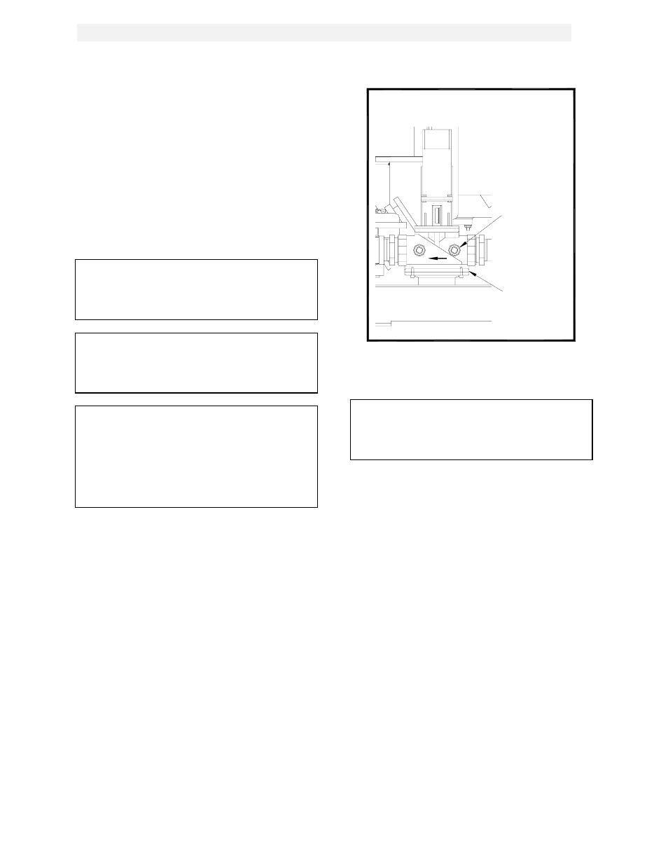
1/4" NPT PLUG
(INSTALL
MANOMETER
HERE)
SSOV
Figure 6.1
1/8” Pipe Plug Position for Manometer
installation
NOTE:
After faulting the unit, the fault message will
be displayed and the fault indicator light will
flash until the CLEAR button is pressed.
6.3 LOW WATER LEVEL FAULT TEST
1. Place the ON/OFF switch in the OFF
position.
2. Close shut-off valves in the supply and
return piping to the unit.
3. Open the drain valve on the unit.
4. Allow air flow into the unit by either opening
the relief valve or by removing the 1/4” plug
in the top of the unit.
5. The LOW WATER LEVEL message will be
displayed and the fault LED will flash after
the water level has gone below the level of
the probe.
6. The ON-OFF switch should not illuminate
when placed in the ON position and the unit
should not start.
7. Close the drain and pressure relief valve or
reinstall the plug in the top of the unit if
removed.