Figure 7.1, Spark ignitor and flame detector location, Maintenance – AERCO KC1000 Boiler equipped with Mod-Box Controller User Manual
Page 39
MAINTENANCE
34
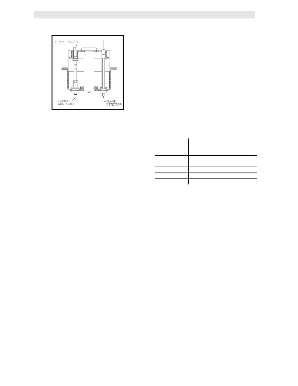
Figure 7.1
Spark Ignitor and Flame Detector Location
To inspect or replace the flame detector:
1. Put the green ON/OFF button on the control
panel to the OFF position and disconnect AC
power to the unit.
2. Disconnect the plastic tubing from the
condensate cup to drain and remove the
rear covers from the unit. Access to the
flame detector may also be gained by
removing the unit’s left side panel
3. Disconnect the flame detector lead wire.
Unscrew the flame detector and remove it
from its guide tube. The detector is flexible
and may be bent to ease its removal.
4. Inspect the detector thoroughly. If eroded,
the detector should be replaced. Otherwise
clean the detector with a fine emery cloth.
5. Reinstall the flame detector hand tight only.
6. Reconnect the flame detector lead wire.
7. Replace the rear cover panels or left side
panel and reconnect the rear covers to the
unit. Replace the condensate cup to drain
tubing.
7.4 COMBUSTION CALIBRATION
Combustion settings must be checked at the
intervals shown in Table 1 as part of the
maintenance requirements. Refer to Sections
4.2 and 4.3 for combustion calibration
instructions.
7.5 SAFETY DEVICE TESTING
Systematic and thorough tests of the operating
and safety devices should be performed to
ensure that they are operating as designed.
Certain code requirements, such as ASME CSD-
1, require that these tests be performed on a
scheduled basis. Test schedules must conform
to local jurisdictions. The results of the tests
should be recorded in a log book. See Section 6-
Safety Device Testing Procedures.
7.6 MANIFOLD AND EXHAUST TUBES
The presence of even trace amounts of
chlorides and/or sulfur, in the combustion air and
fuel sources, can lead to the formation of
deposits on the inside of the exchanger tubes,
the exhaust manifold, and/or the condensate
cup. The degree of deposition is influenced by
the extent of the condensing operation and the
chloride and sulfur levels that vary significantly
from application to application.
The following parts will be necessary for
reassembly after inspection:
GP-122537
Exhaust Manifold to
Combustion Chamber
Gasket
GP-18900
Manifold to Tubesheet
Gasket
GP-18899 Burner
Gasket
GP-122551
Burner Release Gasket
*GP-161151
Combustion Chamber Liner
*Not necessary to change but should be on hand
in case damage occurs during the inspection.
To remove the manifold for inspection:
1. Disconnect AC power and turn off the gas
supply to the unit.
2. Remove the sheet metal covers from the
unit.
3. Disconnect the plastic tubing from the
condensate cup to drain and remove the
rear covers.
4. Remove the condensate cup from under the
unit and the condensate drainage tubing
from the manifold.
5. Remove the flame detector and ignition
cable wires from the flame detector and
ignitor contactor. Remove the flame detector
and ignitor as sections 7.2, and 7.3.
6. Remove the grounding terminal from the
burner by loosening the upper screw and
sliding the connector from the grounding rod.
(See Fig. 7.2)