L-cell – Kistler-Morse KM L-Cell Bolt-On User Manual
Page 85
Appendix G. Alternate Method
G-2
L-Cell
If you do not have a Kistler-Morse Test Meter, use a Digital Multimeter (DMM) to monitor the voltage
output of each L-Cell during installation. Set up the DMM as described below and then follow the installa-
tion procedure for Mounting L-Cell.
Note
The junction box must be mounted and wired to the signal processor and powered up before
following this procedure. See Mounting Junction Box, Wiring L-Cells to Junction Box, and Wiring
Junction Boxes Together and to Signal Processor before proceeding.
1.
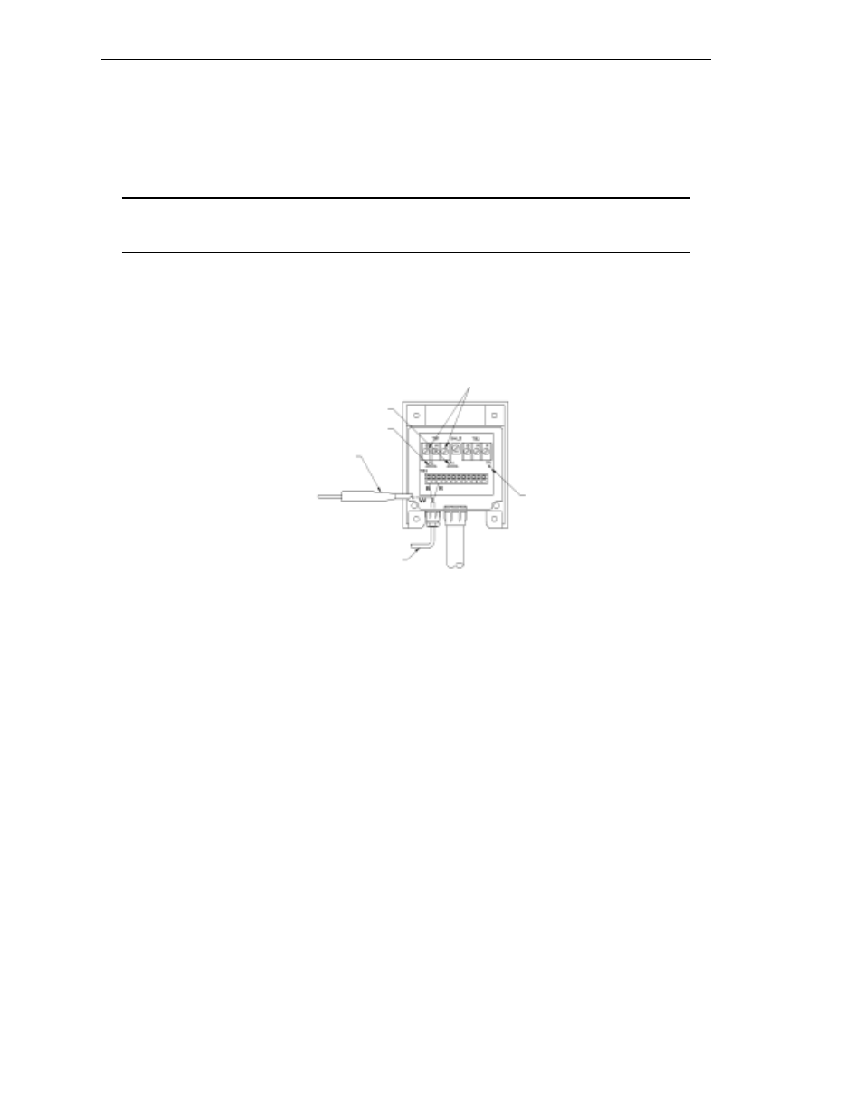
See Figure G-2. Connect the red wire from the L-Cell cable to the R terminal on terminal block TB3 in the
junction box. Connect the black wire to the B terminal on TB3.
Figure G-2. Using DMM to Monitor
Voltage Output
2.
Connect the signal (+) probe of the DMM to the white wire from the L-Cell cable. DO NOT connect the
white wire to the terminal block.
3.
Connect the common (-) probe of the DMM to TP1 on the junction box circuit board. If a test point is
not present, connect the common probe to the lead
of either R1 or R2 nearest the TB2 terminal strip.
4.
Set a voltage range on the DMM that will accommodate a measured range of ± 1 volt.
5.
Complete installation of the L-Cell, using the DMM to monitor the voltage output as you use the T-
handle driver to tighten the screws. See Mounting L-Cell for details.
+ Probe
from DMM
R1
R2
TP1
L-Cell Sensor
Cable
12 VDC Excitation Voltage from
Signal Processor connected
across Black and Red Terminals