L-cell mounting locations – Kistler-Morse KM L-Cell Bolt-On User Manual
Page 15
Chapter 3. L-Cell Installation on Vertical Legs
3-1
Chapter 3: Installation of the L-Cell on
Vertical Legs
Follow the instructions in this chapter only if installing
L-Cells on vertical column legs. Skip this chapter if installing
other options. This chapter describes the mounting locations,
and wiring installation details for L-Cells and their junction
boxes on vertical leg applications.
Follow the procedures below to determine L-Cell mounting locations prior
to beginning installation. Following these procedures will ensure optimal
system performance. Consult KM if special considerations prevent you
from installing L-Cells at the designated locations.
For best performance, L-Cells are mounted on the flanges of the vertical
leg. (See Figure 3-1). An L-Cell Set consists of two L-Cells mounted on
opposite sides of a support leg, at the same elevation.
Note:
Do not install L-Cell on pipe leg. (See Chapter 6: Microcell
Installation)
Always place L-Cells at center of flange, regardless of orienta-
tion of leg to vessel.
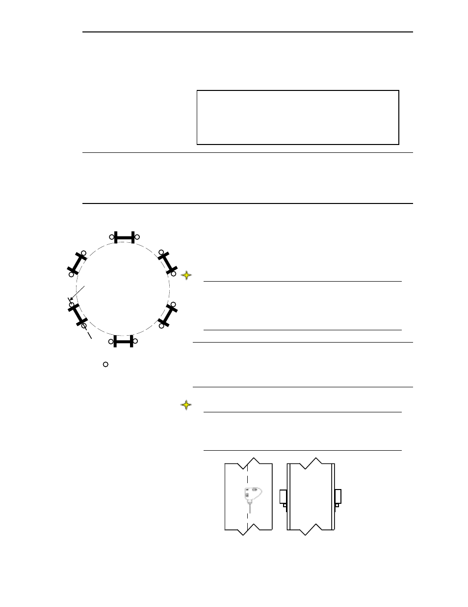
Horizontal Locations of L-Cell Sets
L-Cell sets are placed on each support leg. Refer to Figure 3-2 for the
mounting locations.
Vertical Location of L-Cell Sets
Note
L-Cell locations may be adjusted up to 12” (305mm) vertically to
avoid obstacles. If adjusting locations, maintain the configura-
tion of the L-Cell set (i.e., if you move one L-Cell in the set from
its ideal location, move the other(s) as well).
L-Cell Mounting Locations
Figure 3-2. L-Cell Mounting for
Best Performance
I-Beam
Center L-Cell’s
vertical axis on
Centerline of
Flange (typical)
= Individual L-Cell
Figure 3-1. L-Cell Mounting
Locations