Kistler-Morse KM L-Cell Bolt-On User Manual
Page 36
Chapter 4. L-Cell Installation on Horizontal Beams
4-11
1.
Remove the junction box cover.
• Conduited installation — Install a conduit fitting in the large hole in
the bottom of the junction box.
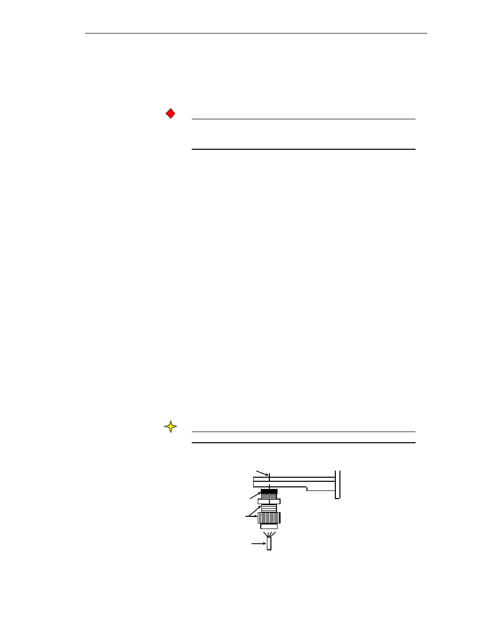
• Non-conduited installation — See Figure 4-17. Spread a generous
bead of sealant around the sides of the PG13.5 cable fittings. Install
the fittings in the two large holes in the bottom of the junction box.
CAUTION
Only use Sikaflex 1A polyurethane sealant or Dow Corning RTV 739
or RTV 738. Other sealants may contain acetic acid, which is harmful
to sensors and electronics.
2.
See Figure 4-18 (conduited installation) or Figure 4-19 (non-conduited
installation). Route the 3-conductor cable through the fitting into the
junction box farthest from the signal processor. Connect wires from the
cable to the TB2 terminal in the junction box: black wire to B terminal,
white wire to W terminal, and red wire to R terminal. Connect the cable
shield wire to the Shield terminal between TB1 and TB2.
3.
Route the cable through conduit/cable tray to the next junction box.
Estimate the required length of cable to the terminal strip, allowing a little
extra for strain relief. Cut the excess cable. Connect wires from the cable
to the TB1 terminal in the junction box: black wire to B terminal, white
wire to W terminal, and red wire to R terminal. Connect the cable shield
wire to the Shield terminal between TB1 and TB2.
4.
Route another 3-conductor cable through the fitting into this junction
box, and attach wires to the TB2 terminal: black wire to B terminal, white
wire to W terminal, and red wire to R terminal. Connect the cable shield
wire to the Shield terminal between TB1 and TB2.
5.
Repeat Steps 3 and 4 until all junction boxes for the vessel are wired
together.
6.
Route the cable from the last junction box through conduit/cable tray to
the signal processor. Refer to the signal processor manual for wiring the
junction box to the signal processor. One vessel takes up one channel in
the signal processor — the channel shows the average value from all the
L-Cells on the vessel supports.
Note
Ground the cable shield only at the signal processor.
Figure 4-17. Inserting Shielded Interconnect
Cable through PG13.5 Fitting and Cap
PG13.5 Fitting
and Cap
Large Hole (typical)
Sealant
Shielded Cable
12
12
12
12
Note: After cable is
connected to terminals,
tighten cap until cable
glands in fitting seal
around cable.