Appendix g: alternate method of checking output, Microcell – Kistler-Morse KM L-Cell Bolt-On User Manual
Page 84
Appendix G. Alternate Method
G-1
Appendix G: Alternate Method of
Checking Output
Microcell
If you do not have a K-M Test Meter, use a Digital Multimeter (DMM) to monitor the voltage output of each
Microcell during installation. Set up the DMM as described below and then follow the installation procedure
for Mounting Microcell.
Note
The junction box must be mounted and wired to the signal processor and powered up before
following this procedure. See Mounting Junction Box, Wiring Microcells to Junction Box, and
Wiring Junction Boxes Together and to Signal Processor before proceeding.
1.
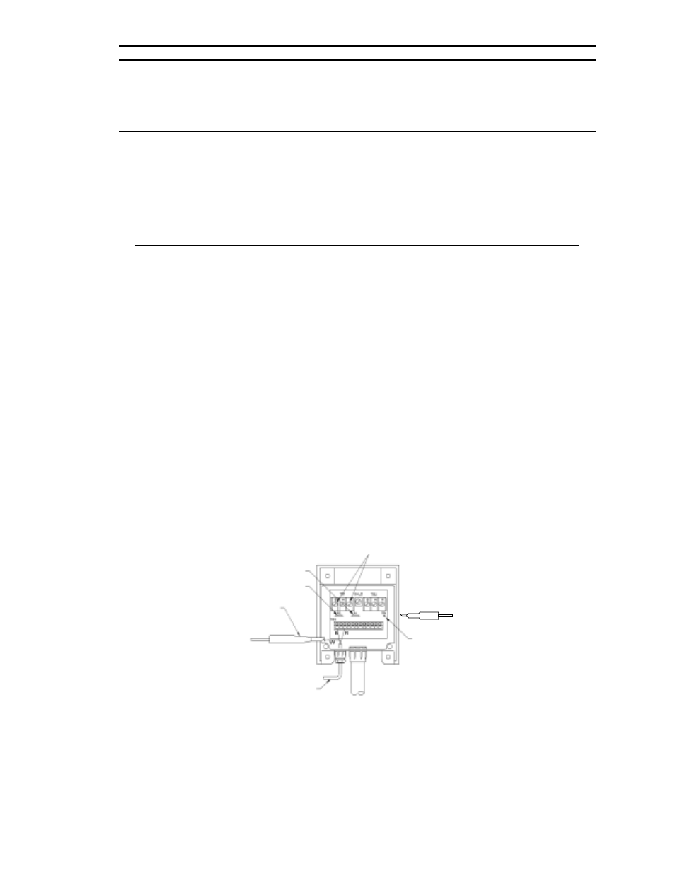
See Figure G-1. Connect the red wire from the Microcell cable to the R terminal on terminal block TB3 in
the junction box. Connect the black wire to the B terminal on TB3.
2.
Connect the signal (+) probe of the DMM to the white wire from the Microcell cable. DO NOT connect
the white wire to the terminal block.
3.
Connect the common (-) probe of the DMM to TP1 on the junction box circuit board. If a test point is
not present, connect the common probe to the lead
of either R1 or R2 nearest the TB2 terminal strip.
4.
Set a voltage range on the DMM that will accommodate a measured range of ± 1 volt.
5.
Complete installation of the Microcell, using the DMM to monitor the voltage output as you tighten the
screws. See Mounting Microcell for your installation.
Figure G-1. Using DMM to Monitor Voltage Output
Connect + Probe from
DMM to White Wire
from Microcell
R1
R2
Microcell
Sensor Cable
12 VDC Excitation Voltage from
Signal Processor connected
across Black and Red Terminals
TP1
Connect
- Probe from DMM
to TP1