Kistler-Morse KM L-Cell Bolt-On User Manual
Page 68
Chapter 6. Microcell Installation on Vertical Pipe Legs
6-11
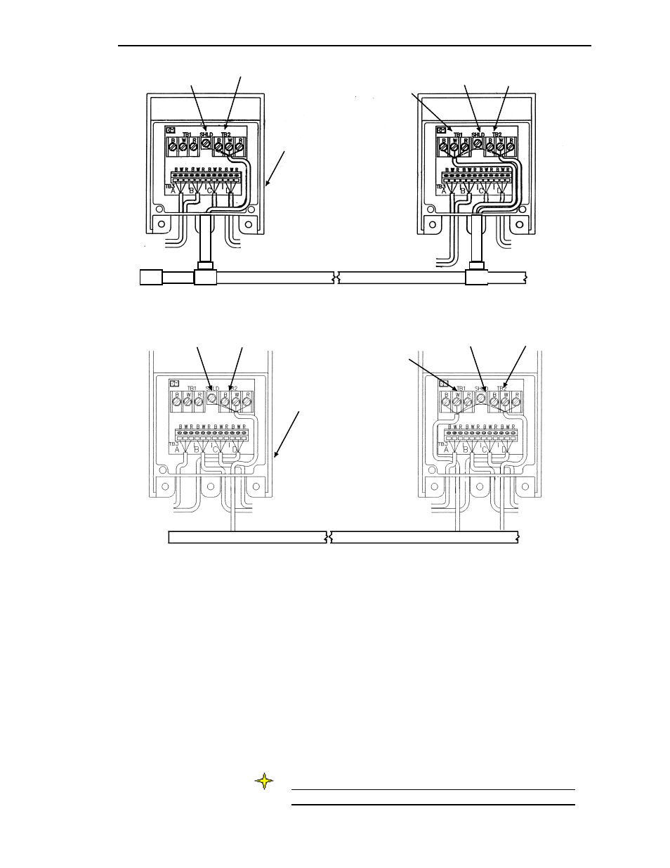
Figure 6-21. Wiring Junction Boxes Together — Non-Conduited Installation
Connect 3-Conductor
Cable to TB2
Connect 3-Conductor
Cable from First
Junction Box to TB1
Connect another
3-Conductor
Cable to TB2
Connect Shield Wire
from Both Cables to
Shield Terminal
Connect Shield
Wire (typical)
To Microcells
(typical)
First
Junction Box
To Next Junction
Box or Signal
Processor
Cable Tray
4.
Route another 3-conductor cable through the fitting into this
junction box, and attach wires to the TB2 terminal: black wire to B
terminal, white wire to W terminal, and red wire to R terminal.
Connect the cable shield wire to the Shield terminal between TB1
and TB2.
5.
Repeat Steps 3 and 4 until all junction boxes for the vessel are wired
together.
6.
Route the cable from the last junction box through conduit/cable
tray to the signal processor. Refer to the signal processor manual
for wiring the junction box to the signal processor. One vessel takes
up one channel in the signal processor — the channel shows the
average value from all the Microcells on the vessel supports.
Note
Ground the cable shield only at the signal processor.
Figure 6-20. Wiring Junction Boxes Together — Conduited Installation
Connect 3-Conductor
Cable to TB2
Connect another
3-Conductor
Cable to TB2
To Next Junction
Box or Signal
Processor
Connect Shield Wire
from Both Cables to
Shield Terminal
Connect Shield Wire
to Shield Terminal
To Microcells (typical)
First
Junction Box
Connect 3-Conductor
Cable from First
Junction Box to TB1