Kistler-Morse KM L-Cell Bolt-On User Manual
Page 27
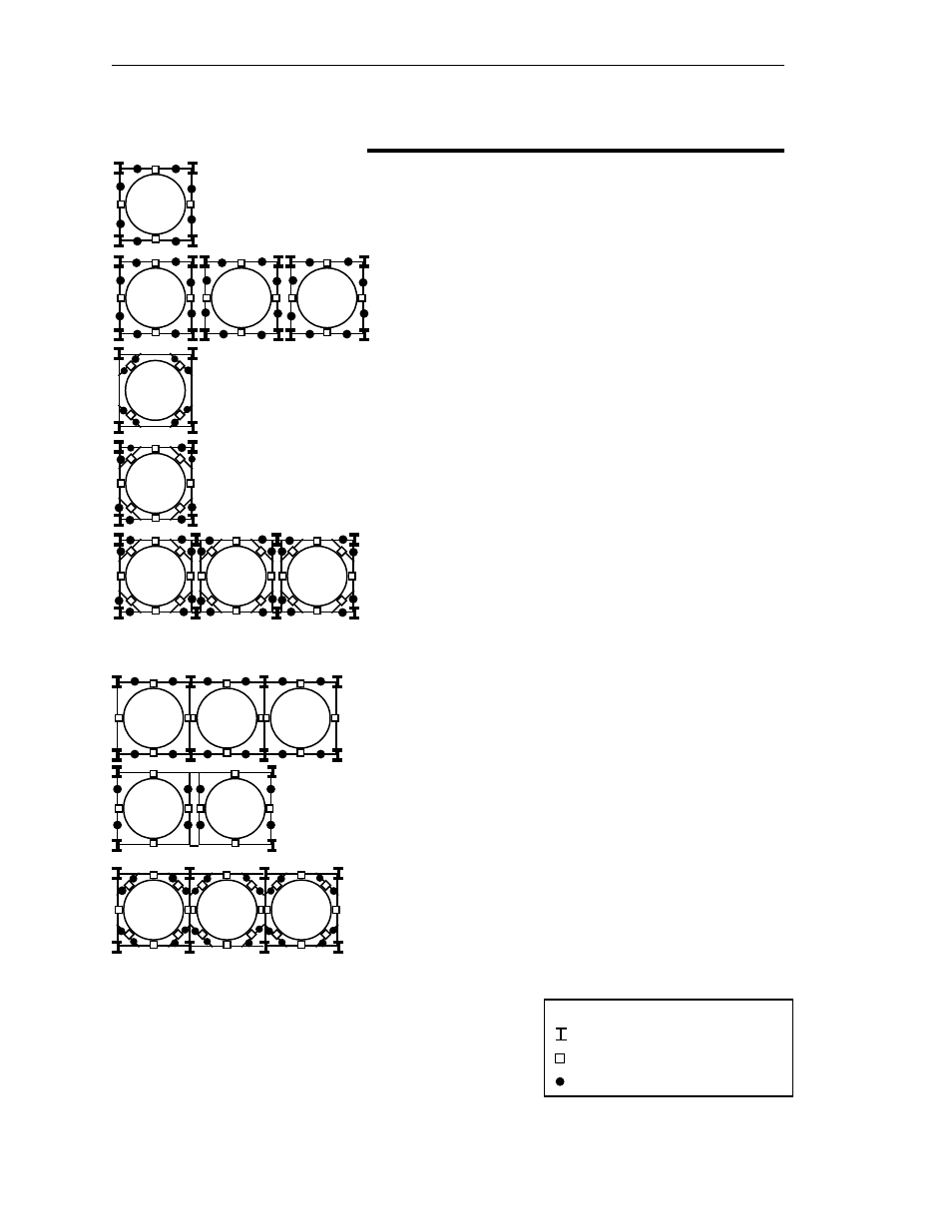
Chapter 4. L-Cell Installation on Horizontal Beams
4-2
# of Support
Points for
Description
Each Vessel
Single vessel — no diagonal beam supports
4
Multiple vessels — no diagonal beam supports,
4
no common beams or common vertical legs
Single vessel — diagonal beam supports,
4
weight supported by diagonal beams only
Single vessel — diagonal beam supports,
8
weight supported by horizontal and
diagonal beams
Multiple vessels — diagonal beam supports,
8
weight supported by horizontal and diagonal
beams, no common beams, common
vertical legs
Multiple vessels — no diagonal beam supports,
4
common internal lateral beams, common
internal vertical legs
(Note: This application will produce some
degree of interference between vessels.)
Multiple vessels — no diagonal beam supports,
4
independent internal lateral beams, common
longitudinal beams
(Note: This application will produce some
degree of interference between vessels.)
Multiple vessels — diagonal beam supports,
8
weight supported by horizontal and
diagonal beams, common internal lateral beams,
common internal vertical legs
(Note: This application will produce some
degree of interference between vessels.)
Series 500 — Independent Beams
501
502
502
502
552
553
553
553
551
602
602
601
601
601
651
651
651
Series 600 — Common Horizontal Lateral
and/or Longitudinal Beams
Notes
:
1.
Illustrations for Series 501, 502, 551, 552, 553, and 651 show
L-Cells in relationship to the load points.
2.
If your application differs from the above, contact K-M for
application assistance.
Figure 4-2. L-Cell Mounting Locations
Legend:
= vertical leg
= vessel support point
= mounting location for L-Cell set