Kistler-Morse KM L-Cell Bolt-On User Manual
Page 38
Chapter 5. L-Cell Installation on Skirt-Supported Vessels
5-1
Chapter 5: Installation of the L-Cell on
Skirt Supported Vessels
Distribution of L-Cells and
Junction Boxes Around Vessel-Carbon
Steel
Bolted, Skirt-Supported Vessels
See Figures 5-3 and 5-4. The skirt-supported
vessel manufacturers’ industry has standardized
on bolted, skirt-supported vessel diameters and
number of panels per diameter. Typically, the
panels are approximately 5’ (1.5m) wide x 8’ (2.4m)
high, with some overlap between panels. The
mounting locations shown in Figures 5-3 and 5-4
are based on this industry standard.
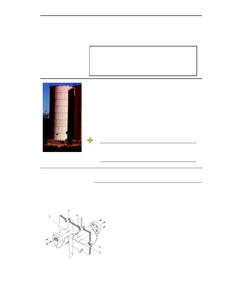
Figure 5-2. L-Cell Set Mounting
Panel
2.50” (63.5mm)
3.50”
(89mm)
Panel
Cable Routing Thru Hole
3
/
16
” (4.8mm) Diameter
Follow the instructions in this chapter only if you are installing
L-Cells on skirt-supported vessels (carbon steel or aluminum).
This chapter describes the mounting locations, installation
details, and wiring details for L-Cells and junction boxes. Follow
all instructions carefully to ensure proper system operation.
Based on information you provided on the Application Data Form, KM
marked the form to show approximate L-Cell and junction box locations.
The marked form was returned to you as part of the L-Cell shipment.
Consult KM if the information you provided on the form does not reflect
the current vessel configuration.
Read the installation procedures and follow the procedures in Marking
Mounting Locations to determine and mark the exact mounting locations
of the L-Cells and junction boxes on your vessel, prior to beginning
installation. This will ensure optimal performance of the system. Consult
KM if special considerations prevent you from installing L-Cells and/or
junction boxes at the designated locations.
Note
If you have a skirted silo with spars, legs, or any load-bearing
structures that are in addition to the skirt, consult KM for applica-
tion and mounting location assistance. Stress distribution for these
vessels is complex and can adversely affect system performance.
L-Cell Sets
See Figure 5-2. L-Cells are mounted around skirt-supported vessels in
sets of two. For each set, one L-Cell is mounted on the outside and one on
the inside of the skirt, with a 2.50” (63.5mm) horizontal offset.
General Mounting Information
Figure 5-1. Skirted Silo