Kistler-Morse KM L-Cell Bolt-On User Manual
Page 20
Chapter 3. L-Cell Installation on Vertical Legs
3-6
8.
Prior to installing the environmental cover(s), ensure the mating
surface(s) on the leg is free of dirt and grease. Reclean if necessary,
being careful not to remove the rust inhibitor on the bare metal.
9.
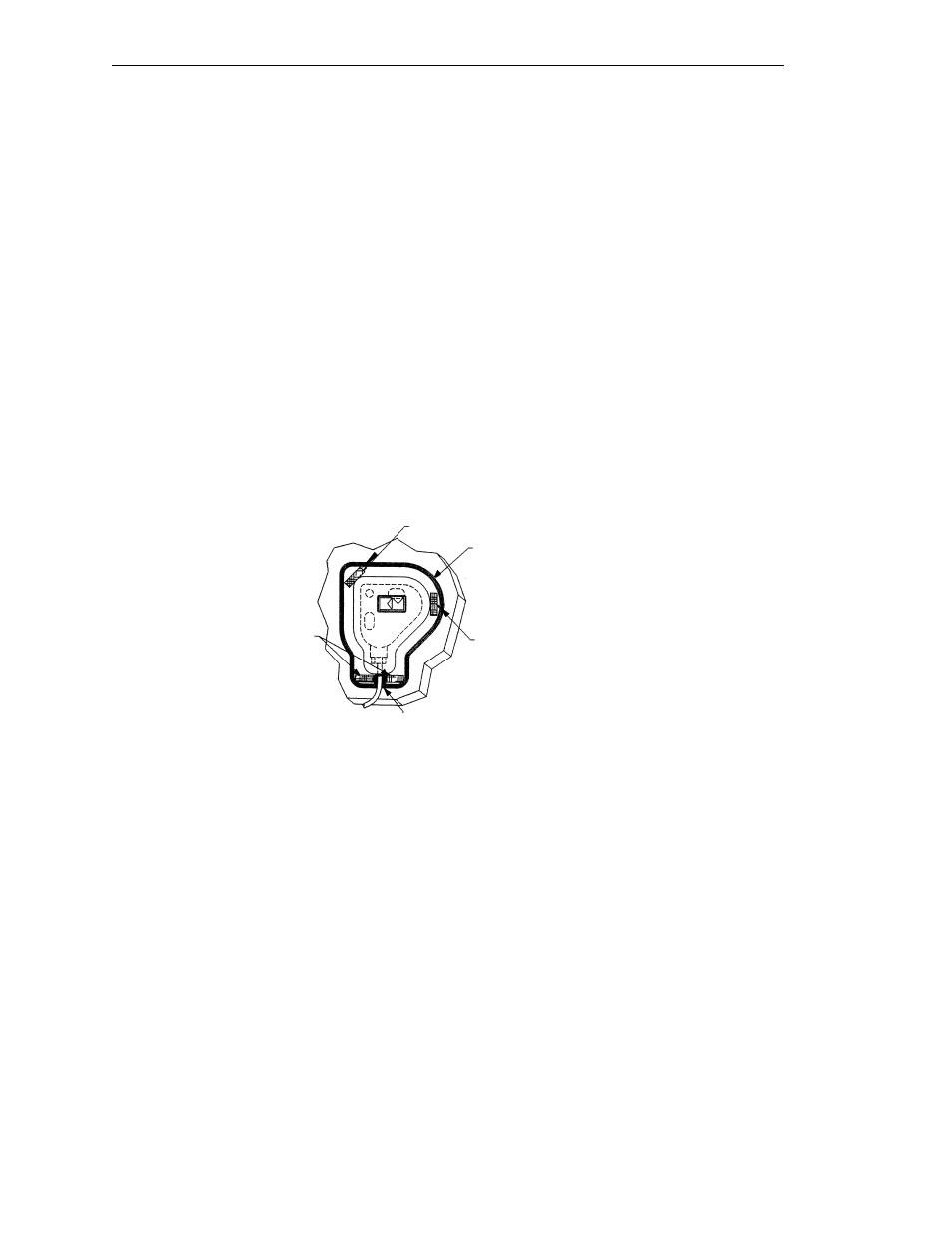
Fig 3-13. Peel the protective backing from the double-sided tape on the
environmental cover’s inside flange.
A. Align the environmental cover over the installed L-Cell, with the
cable through the cover’s exit channel. Press the cover onto mount-
ing surface.
B. Spread a
1
/
8
” (3.2mm) bead of sealant around the joint between the
cover and mounting surface. Add extra sealant to the cable exit
channel and between cable and skirt.
C. Use your finger to smooth the sealant around all edges and joints,
eliminating areas where moisture may pool, especially along the top
edge. Verify that the sealant forms a continuous, watertight seal.
Ensure the cable exit channel is completely sealed.
10. If you created any holes that go completely through the support metal,
spread sealant (Sikaflex 1A polyurethane sealant or Dow Corning RTV
739 or RTV 738) over the open holes. Use your finger to press sealant
into each hole.
Cable Exit Channel
Tape
1/8” (3.2mm)
Bead
All-Around
(wipe smooth)
Tape
Tape
Figure 3-13. Environmental Cover