Mounting the l-cell – Kistler-Morse KM L-Cell Bolt-On User Manual
Page 18
Chapter 3. L-Cell Installation on Vertical Legs
3-4
1.
Wipe down a 5” by 2
1
/
4
” (127 by 57mm) surface, centered on the
template mounting hole, with degreaser. This cleans the bare
metal and adjacent mounting surface for the environmental cover.
2.
Apply a thin coat of KM rust inhibitor to the bare metal surface
for the L-Cell. (Fig 3-10)
3.
Connect the L-Cell’s red, black, and white wires to the corre-
sponding terminals on the KM Test Meter. Turn on the power to
the Test Meter and set the Simulate/Test switch to the Test
position. (Fig 3-11)
Note
If a KM Test Meter is not available, refer to Appendix G,
Alternate Method for Checking Output, before proceeding.
4.
With the cable end down, align an L-Cell with its mounting holes.
Fasten the L-Cell loosely to the leg using the three #6-32 x
5
/
8
”
socket head cap screws. Do not tighten the screws. If the voltage
goes outside the range -200 to +200 mV, immediately loosen the
screw(s).
4.
Drill the L-Cell mounting holes with the #36 drill bit,
using the template guides (Fig. 3-9) as follows:
A. Drill hole #2.
B. Insert a spare drill bit through hole #2 in the
template to hold the template securely in place.
C. Drill hole #1 and #3. Remove the spare drill bit from
hole #2.
5.
Tap the mounting holes:
A. Loosen the screw securing the template and rotate
the template until the tap guide is aligned with hole
#1. Retighten the screw.
B. Using the tap guide, thread hole #1 with the #6-32
tap.
C. Repeat steps A and B for hole #2 and #3.
6.
Repeat Surface Preparation and Drill/Tap for the
second L-Cell.
7.
Remove burrs from all the holes created.
Mounting the L-Cell
CAUTION
Do not install L-Cells in
the rain.
Do not trap moisture under
the environmental cover.
CAUTION
Do not apply rust inhibitor
beyond this area, or the
environmental cover will
not adhere properly.
Fig. 3-10: Apply rust inhibitor.
Fig. 3-11: Test L-Cell
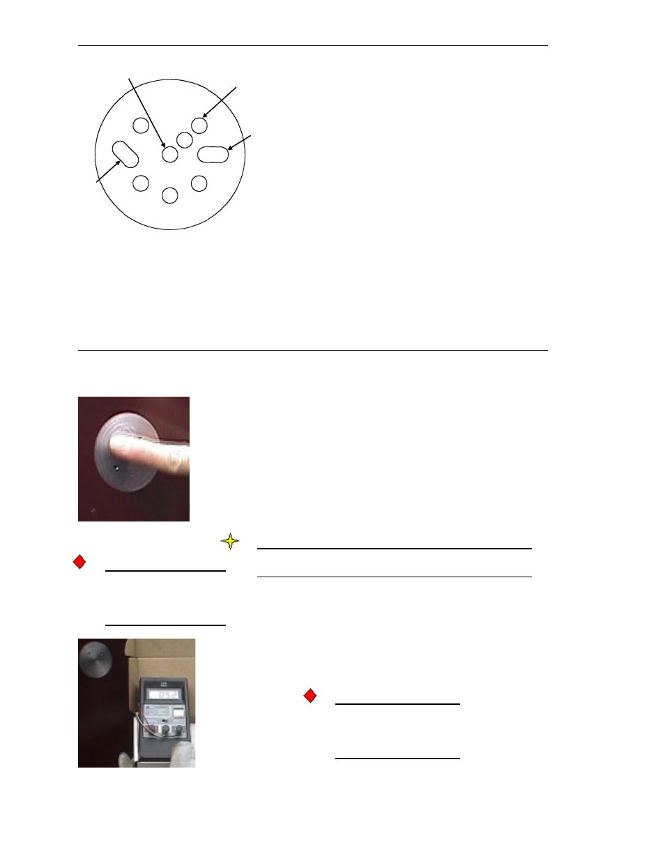
Figure 3-9. Drill and Tap Template
Template Mounting Hole
(mount here with #6-32 x 1
5
/
8
” screw)
0° Level
Bubble
45°
Level
Bubble
Notes:
1. After L-Cell mounting holes drilled, rotate template to
use tap guide to tap holes.
2. Holes #4 and 5B and 45° bubble not used for this
application.
2
3
1
4
5A
5B
Tap Guide
Drill Guide
(typical,
# 1, 2, and 3)