Installing microcells – Kistler-Morse KM L-Cell Bolt-On User Manual
Page 60
Chapter 6. Microcell Installation on Vertical Pipe Legs
6-3
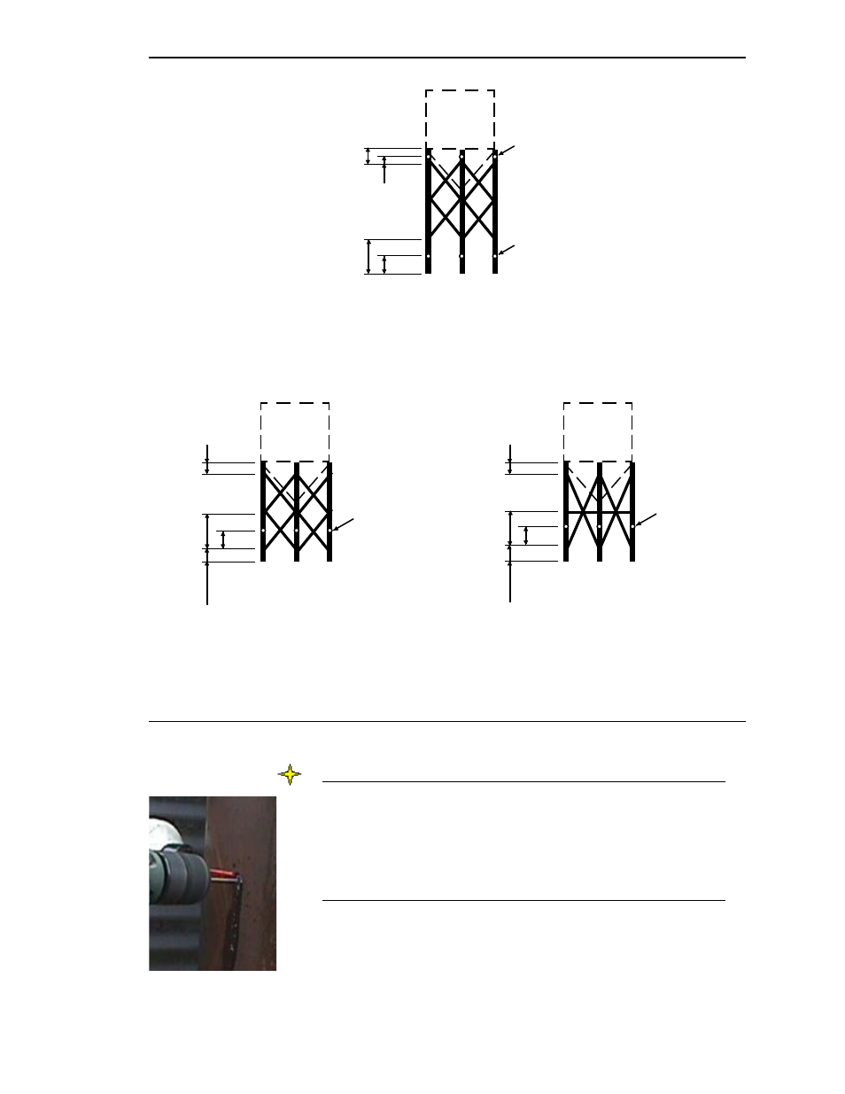
Figure 6-4. Vertical Location of Microcell Sets
for Legs with Braces and with Free Leg
greater than minH
‘Free Leg’
H —
minH
1
/
2
H
Microcell sets
mounted at
mid-height of
free leg
(typical)
Alternate
location —
Microcell sets
mounted at
mid-height of
free leg at
top (typical)
‘Free Leg’
H —
minH
1
/
2
H
Figure 6-5. Vertical Location of Microcell Sets
for Legs with Braces and with Free Leg less
than minH
H
1
/
2
H
Microcell set
mounted at
mid-point
between
lowest
braces
(typical)
‘Free Leg’
less than
minH
Alternate ‘Free
Leg’ less than
minH
H
1
/
2
H
‘Free Leg’
less than
minH
Alternate ‘Free
Leg’ less than
minH
Microcell set
mounted at
mid-point
between
lowest
braces
(typical)
Notes
1. Use lubricating fluid (Relton RapidTap
®
Heavy Duty Cutting Fluid or
equivalent) when drilling and tapping.
2. Drilling and tapping instructions assume metal thickness greater
than
3
/4” (19mm). If the thickness is less, drill all the way through the
metal and tap until cutting complete threads through the other side.
Minimum metal thickness is 0.1875” (5mm), which provides six
thread engagement.
Surface Preparation
1.
See Figure 6-6. At the center of the vertical Microcell mounting location,
drill a
3
/4” (19mm) deep hole with the #29 drill bit. This produces the
template mounting hole.
Installing Microcells
Figure 6-6. Drill
mounting hole