Mounting the junction box, Mounting location, Junction box installation – Kistler-Morse KM L-Cell Bolt-On User Manual
Page 21
Chapter 3. L-Cell Installation on Vertical Legs
3-7
Mounting the Junction Box
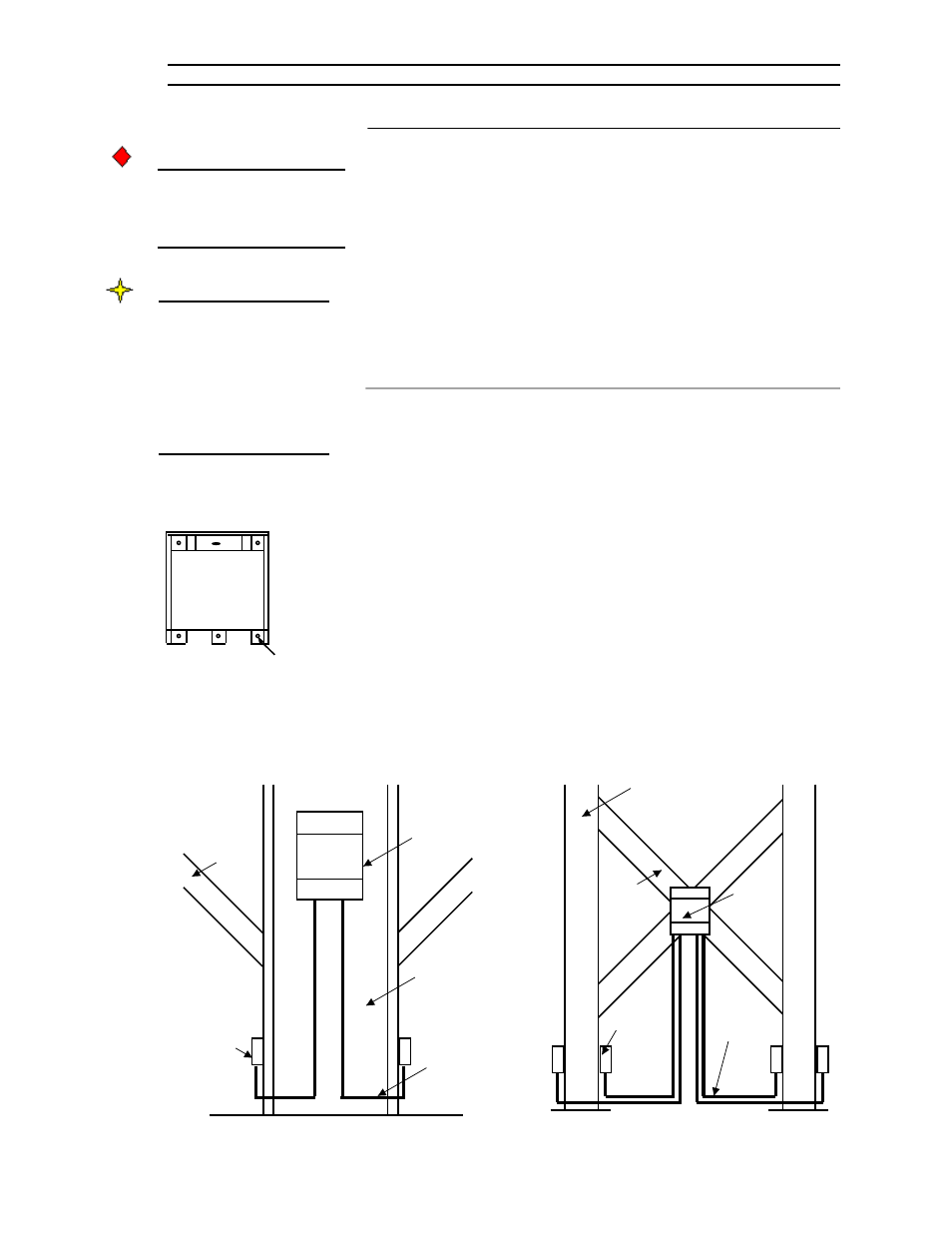
Figure 3-14. Junction
Box Mounting
Outside Mounting Holes for
Flat Surfaces (4 places)
CAUTION
Do not install junction boxes
in the rain. Moisture in the
junction box will cause
corrosion and system errors.
Note
Junction box mounting
hardware is not supplied
by KM. KM recommends
#8-32 socket head cap
screws and flat washers.
The instructions below
reflect this recommenda-
tion.
Figure 3-15. Possible Junction Box Mounting Locations
L-Cell
Drip Loop
Junction
Box
Support
Leg
Support Leg
Junction
Box
Brace
Drip
Loop
L-Cell
Brace
Mounting Location
Each junction box can be wired to a maximum of four L-Cells:
•
L-Cells — one junction box can be wired to L-Cells from two support
legs (two L-Cells on each support leg) if the legs are sufficiently close
to each other to allow the L-Cell cables to reach.
See Figure 3-15. Locate the junction box on the support leg web or on a
brace. Vertically, locate junction boxes at a convenient height, approxi-
mately 4’ (1.2m) from the ground. The exact location of the junction box is
not critical, but ensure you have sufficient cable length and that a drip loop
will be formed by the L-Cell cables when wired to the junction box.
Junction Box Installation
1.
Remove the junction box cover.
2.
See Figure 3-14. Hold the junction box at the previously marked
mounting location. Mark the mounting holes. Mark the four outside
mounting holes (mounting on a flat surface), such as an I-Beam.
3.
Drill and tap the mounting holes with a #29 drill bit and #8-32 tap.
4.
Mount the junction box with #8-32 socket head cap screws and flat
washers. Tighten the screws until snug. Replace the junction box cover
and screws if not ready to begin wiring, to ensure no moisture enters
the junction box.