Connecting cables, 1 sj-m series operations, Setup overview – KEYENCE SJ-M201 User Manual
Page 7: Changing settings, Sj-m series operations
7
2-2
Connection and Installation
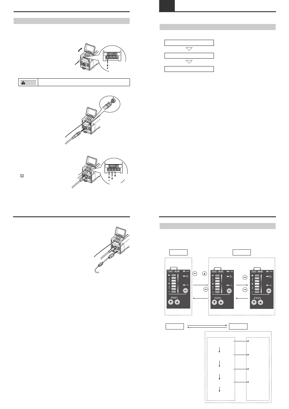
Connecting Cables
When you have finished installing the Static Elimination Head, connect the earth lead, Static
Elimination Head connector cable and power supply.
■ Connecting the earth lead
Open the terminal plate cover on the Controller
Unit, and connect the earth lead to the GND
connection terminal.
Be sure to connect a Class D earth (maximum
resistance of 100 Ohms).
■ Connecting the cable
Connect the Static Elimination Head
connector cable to the Controller Unit.
Connect this cable with the power
turned OFF.
When installing the Controller Unit
away from the Static Elimination
Head, use the optional extension
cable (SJ-C3).
■ Connecting the power supply
Connect the power supply according to
either of the following methods.
24 VDC power supply
Connect a 24 VDC output power supply
having sufficient power capacity margin to
the power terminals (terminals (5) and (6))
"Controller Unit (I/O terminal section)" (page
4)
To prevent electric shock and to ensure accurate static elimination, be sure
to connect a Class D earth (maximum resistance of 100 Ohms).
Be sure to connect
a Class D earth
(maximum resistance
of 100 Ohms).
CAUTION
Match and connect
the end of the connector
cable to the inlet on the
Controller Unit.
To 24 VDC
power supply
To 24 VDC
power supply
2-2
Connection and Installation
Using the dedicated AC adapter (SJ-U2)
Connect the dedicated AC adapter to the connector on
the side of the Controller Unit.
The dedicated AC adapter is available as an option.
3-1
SJ-M Series Operations
This section describes the setting and operation of the SJ-M Series.
Setup Overview
A brief overview of the setup procedure for the SJ-M Series is provided below.
Operation mode selection
1. Operation mode selection
Select the operation mode using the operation
mode selector switch.
Settings adjustment
2. Settings adjustment
Change the settings for the SJ-M201.
Ion balance adjustment
3. Ion balance adjustment
The zero point, the point of reference for the
I.C.C. function, can be adjusted.
(* The zero point should only be adjusted when
necessary.)
3-1
SJ-M Series Operations
Changing settings
■ Setting adjustment overview
This section provides details regarding settings and a brief overview of the setup procedure used for
changing operation modes on the SJ-M Series.
Setting items
Run mode
Setup mode
[Setting items]
[Detailed settings]
Either lights up
Normal operation state.
Select setting items.
Select detailed settings.
Blink alternately
Blink alternately fast
Hold down
and
simultaneously
for at least 1
second.
Hold down
for at least
1 second.
Press
for a
short time.
Press
for a
short time.
Run mode
Setup mode
[Setting items]
[Detailed settings]
Ion level alarm
sensitivity setup
Sensitivity: High
Sensitivity: Medium
Sensitivity: Low
Sensitivity: None
Sensitivity: High
Sensitivity: Medium
Sensitivity: Low
Sensitivity: None
Condition alarm
sensitivity setup
I.C.C. ON
I.C.C. OFF
I.C.C. ON/OFF
setting
High temperature
use
Normal
temperature
High temperature
use setting
Initialization of
settings