2 connection and installation, Installing the nozzle/tube, Installing the sj-m series – KEYENCE SJ-M201 User Manual
Page 6: Connection and installation
6
2-1
Before Installation
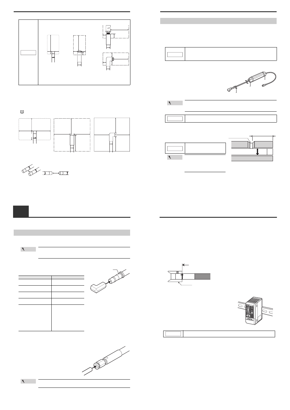
■ Interference
The Static Elimination Head may not function properly if there is a conductor (earthed body) located
nearby or if two or more units are used close to each other. In such an installation, refer to the figure
below and maintain the indicated distance between the conductor (earthed body). If a conductor
(earthed body) is located inside the distances indicated below, adjust using the ion balance manual
setup.
"Ion Balance Adjustment Function" (page 9)
When two SJ-M Series units are used, refer to the figures below, and install the units so that the
following distances are maintained between the two Static Elimination Heads.
●
SJ-M021(G)
• Do not install the Static Elimination Head at locations where moving parts
of other equipment and machinery may place stress on the cable. Doing so
might cause the SJ-M021(G) Series to malfunction.
NOTICE
200 mm
or more
20 mm
or more
10 mm
or more
20 mm
or more
20 mm or more
10 mm
or more
200 mm or more
10 mm
or more
20 mm or more
20 mm or more
200 mm or more
When SJ-MS2
is used
When SJ-ML1
is used
When SJ-MS1
is used
200 mm
or more
20 mm
or more
10 mm
or more
20 mm
or more
60 mm or more
away from the
nozzle or air outlet
60 mm or more
60 mm or more
60 mm
or more
60 mm or
more away
from the
nozzle or
air outlet
60 mm or more
60 mm or more
60 mm
or more
●
SJ-M021(G)
60mm or more
60mm
or more
60mm
or more
35mm or more
●
SJ-MS*
●
SJ-ML*
60 mm or more
60 mm or more
2-2
Connection and Installation
This section describes how to connect and install the Static Elimination Head and Controller Unit.
Installing the nozzle/tube
Install the nozzle and tube to the Static Elimination Head by following the procedures below.
■ Installing the nozzle
Attach the nozzle to SJ-M021(G). Attach and tighten
the nozzle mounting fixture to the nozzle to fasten it in place.
■ Installing the tube
An air tube is applicable to SJ-MS3/4 and SJ-ML3/4.
Use air tube part number OP-75350 (PFA tube 500 mm).
Static elimination power varies depending on the length
of the air tube. Check the length carefully before use.
It is recommended that this installation be done prior to "Installing the Static
Elimination Head" in the next section. If not, it may be difficult to install the
Static Elimination Head.
Point
Model name
Fastening torque
Between nozzle and nozzle
mounting fixture
2 N·m or less
SJ-MS2/ML2
(between head and adapter)
2–3 N·m or less
SJ-MS3/ML3
(between head and adapter)
7 N·m or less
SJ-MS4/ML4
(between head and adapter)
7 N·m or less
SJ-MS1/ML1
(between resin head and
adapter)
Fasten manually until it stops.
Then use a tool, such as a
wrench, and rotate approx. 2
or 3 more times. Fix in the
desired direction. If you fasten
a screw too tightly, this may
result in breakage. Insufficient
fastening may result in loose
connection or leakage.
Nozzle mounting fixture
Before using SJ-MS3/4 or SJ-ML3/4 with an air tube mounted, turn OFF the
"I.C.C. ON/OFF setting" (page 8).
Point
2-2
Connection and Installation
Installing the SJ-M Series
Install the SJ-M Series at locations where static electricity is generated or is likely to be generated.
■ Installing the Static Elimination Head
There are two ways of installing the Static Elimination Head, with or without the mounting fixtures.
●
When the mounting fixture is used:
When installing the SJ-M021(G), prepare tapped
mounting holes, and install the SJ-M021(G) with M3
screws at a tightening torque of 1 Nm or less (M4
screws: 1 Nm or less).
The M3 screws and bundling band for fastening the
mounting fixture must be prepared separately.
●
When the mounting fixture is not used:
When mounting the SJ-M021(G) using the M3 set
screws, tighten at a torque of 0.1 Nm or less.
When installing the SJ-M Series, observe the minimum bending radius of all
provided cables. Also, do not install the SJ-M Series with the cables
deformed by staples or other objects. Doing so might cause the SJ-M Series
to malfunction.
NOTICE
Install the mounting fixture within the allowable mounting fixture range indi-
cated in the external dimension drawings. Otherwise, static may not be elimi-
nated properly.
Make a space of 30 mm or more around the drive unit. Otherwise, the unit
may be damaged.
M3 tap
M4 tap
• SJ-M021(G)
Point
NOTICE
Limit the tightening torque to
0.1Nm. Exceeding this torque
might damage the set screws.
Install within the allowable
mounting fixture range indicated
in the external dimension draw-
ings. Otherwise, static may not
be eliminated properly.
M3 set screw (flat)
28 mm or more
NOTICE
Point
2-2
Connection and Installation
■ Installing the discharge prevention cap (option)
An optional discharge prevention cap is available to prevent the risk of accidentally touching the
Static Elimination Head and causing discharge during maintenance work, for example. Use this cap
if necessary.
■ Installing the cap
Install the discharge prevention cap as shown in the following figures, and fasten in place using the
set screws (provided).
(Tightening torque: SJ-M021(G): 0.04 Nm or less)
■ Installing the Controller unit
Install and fasten in place
so that the end surface of
the cap is at this position.
OP-75354
●
SJ-021(G) (cross-section view)
Mount the Controller Unit on the DIN rail.
The SJ-M201 cannot be connected to the SJ-M010/M020(G).
NOTICE