Precautions on regulations and standards, 1 features of the sj-m series, Outline of the sj-m series – KEYENCE SJ-M201 User Manual
Page 2: Features of the sj-m series
2
n SJ-M Series Warning label
A WARNING label is affixed on the SJ-M Series to ensure safety. Read the description on this
WARNING label to ensure correct use of the SJ-M Series.
n Installation Precautions
n About Warm-up
WARNING la
b
els in Japanese, German, French, Italian and Chinese (Simplified) are provided.
Use them as necessary.
Avoid installing the SJ-M Series in the following locations as this may cause
accidents.
• Locations directly subject to vibration and shock
• Locations subject to ambient temperature outside of the 0°C to +40°C
range (excluding the High-voltage Cable Unit)
• Locations subject to ambient temperature outside of the 0°C to +80°C
range (High-voltage Cable Unit)
• Locations subject to ambient humidity outside of the 35 to 65%RH range
(condensation not allowed) (excluding the High-voltage Cable Unit)
• Locations subject to ambient humidity outside of the derating range
(condensation not allowed) indicated in the specifications (High-voltage
Cable Unit)
• Locations subject to sudden changes in temperature
• Locations subject directly to blasts from air conditioners
• Locations subject to volatile or flammable substance, solvents or
corrosive gases
• Locations subject to large amounts of dirt, and dust, salt, iron and oil
smoke
• Locations that may be splashed with water, oil or chemical mist
• Locations where strong magnetic and electrical fields are generated
CAUTION
After turning the SJ-M Series ON, wait for about 20 minutes to allow the ion
balance to stabilize.
Point
■ Other Precautions
• Be sure to follow all procedures described in each section of this
instruction manual.
• This SJ-M201 Series uses EEPROM. Do not power off the unit while it is
being set.
Install the tip of the SJ-M021(G) paying attention to the following point.
z
Install the Static Elimination Head away from the wall or surrounding
objects.
•
SJ-M021(G)
z
Protect the area around the tip of the Static Elimination Head with silicon,
fluoro-resin or other highly ozone-resistant resin. Ozone that is generated
may cause the metal or resin on the SJ-M021(G) to rust, corrode or
deteriorate.
•
SJ-M021(G)
• Do not install the Static Elimination Head at locations where moving parts
of other equipment and machinery may place stress on the cable. Doing so
might cause the SJ-M021(G) to malfunction.
WARNING
CAUTION
The section marked by "*" must not touch the conductor (earthed body).
The adapter nozzle must not touch the conductor (earthed body).
23mm*
10 mm or more
10 mm
or more
10 mm or more
10 mm
or more
Requires 10 mm or more away
from the air outlet
*
200 mm
or more
20 mm
or more
10 mm
or more
20 mm
or more
20 mm or more
10 mm
or more
200 mm or more
10 mm
or more
20 mm or more
20 mm or more
200 mm or more
When SJ-MS2
is used
When SJ-ML1
is used
When SJ-MS1
is used
200 mm
or more
20 mm
or more
10 mm
or more
20 mm
or more
200 mm
or more
20 mm
or more
10 mm
or more
20 mm
or more
200 mm
or more
20 mm
or more
10 mm
or more
20 mm
or more
When SJ-MS3 is used
When SJ-ML2 is used
Precautions on Re
g
ulations and Standards
n CE Marking
Keyence corporation has confirmed that this product complies with the essential requirements of the
applicable EC Directives, based on the following specifications. Be sure to consider the following
specifications when using this product in the Member States of European Union.
l
EMC Directive (2004/108/EC)
•
Applicable Standard
EMI
: EN61326-1, ClassA
EMS : EN61326-1
•
Be sure to provide a ground when installing the SJ-M Series.
•
The length of all input/output cables must be less than or equal to 30 m.
•
Attach a one-loop ferrite core onto the High-voltage Cable Unit and pass the connector cable once
through the core.
•
The following ferrite core is recommended:
SFC-10 made by KITAGAWA INDUSTRIES CO,LTD.
Remarks:
These specifications do not give any guarantee that the end-product with this product incorporated
complies with the essential requirements of EMC Directive. The manufacturer of the end-product is
solely responsible for the compliance on the end-product itself according to EMC Directive.
l
Low-Voltage Directive (2006/95/EC)
•
Applicable Standard : EN61010-1
•
Overvoltage category I
•
Use this product under pollution degree 2
•
Use this product at the altitude of 2000 m or less.
•
Indoor use only.
•
Use the following power supply.
- The power supply that satisfies the requirements of the Limited Power Source specifications
stipulated in EN60950 and certified by European third-party certification organization
- Keyence Corporation AC adapter (SJ-U1/SJ-U2)
n CSA Certificate
This product complies with the following CSA and UL standards and has been certified by CSA . Be
sure to consider the following specifications when using this product as a product certified by CSA.
•
Applicable Standard : CAN/CSA C22.2 No.61010-1,
UL61010-1
•
Overvoltage category I
•
Use this product under pollution degree 2
•
Use this product at the altitude of 2000 m or less.
•
Indoor use only.
•
Use the following power supply.
- CSA/UL-listed power supply that provides Class 2 output as defined in the CEC (Canadian
Electrical Code) and NEC (National Electrical Code)
- CSA/UL power supply that has been evaluated as a Limited Power Source as defined in
CAN/ CSA-C22.2 No. 60950-1/UL60950-1
- Keyence Corporation AC adapter (SJ-U1/SJ-U2)
1-1
Features of the SJ-M Series
This section describes an outline of the functions and features of the SJ-M Series.
Outline of the SJ-M Series
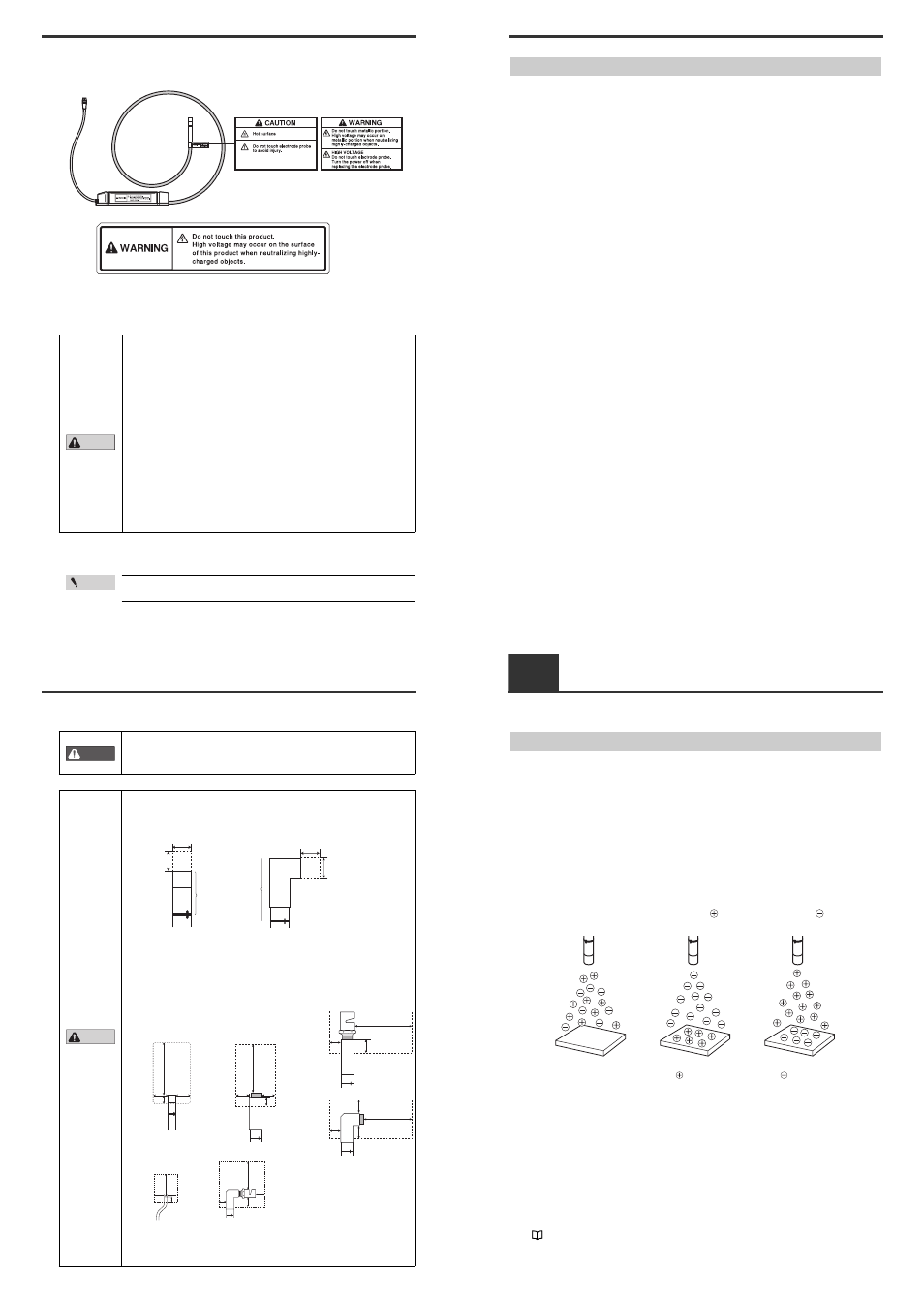
■ Pulse AC method
The SJ-M Series uses a pulse AC method that generates + and – charged air ions from a single
electrode probe. This system ensures a maximum ion level per unit time, and therefore high-speed
static elimination. The SJ-M Series also automatically controls the level of + and – ions generated
based on the charged state of the target object. This enables high-speed and high-precision static
elimination.
■ I.C.C. (Ion Current Control) method
This control method calculates the charged level of the target object by sensing the state of ion
current that arises due to the potential difference between the electrode on the Static Elimination Head
and GND. Optimum static elimination based on the state of the target object can be performed by
rapidly supplying the optimum ions suited to the polarity and charged level of the target object.
■ Ion monitor functions
●
Charge monitor
The integrated ion monitor allows you to see how much the target object is charged by + or – ions.
This monitor also allows you to confirm at a glance how static elimination is being performed.
●
Ion level monitor
The ion level currently being generated by the Static Elimination Head is monitored at all times so that
drops in the generated ion level can be diagnosed on the unit. The generated ion level is indicated by
LEDs and an alarm can be output when the generated ions fall below a certain level. This allows you
to monitor the influence of a dirty electrode probe in advance.
"Ion Monitor Functions" (page 10)
Regular state
Target object in
non-charged state
Elimination of ions
from target object
Elimination of ions
from target object
Target object
charged
Target object
charged