Controller unit (i/o terminal section), 1 before installation, About static elimination performance – KEYENCE SJ-M201 User Manual
Page 4: Before installation
4
1-3
Names and Functions of Parts
Controller Unit (I/O terminal section)
■ Input circuit diagram
■ Output circuit diagram
Number
Name
Function
(1)
Condition alarm output
terminal
Outputs when static elimination performance is influenced by excessive
charge. (N.O.)
(2)
Ion level alarm output
terminal
Outputs when the ion emission level drops. (N.O.)
(3)
Static elimination stop input
terminal
Static elimination can be turned ON/OFF by shorting this terminal with
(6).
(4)
Ground terminal
Be sure to connect a Class D earth (maximum resistance of 100 Ohms).
(5)
DC power terminal
24 VDC ±10%
(6)
0V terminal
0V for power and 0V for I/O
(7)
Alarm output terminal
Outputs when an alarm occurs. (N.C.)
(1)
(4)
(5)
(6)
(7)
(2)
(3)
+24V
3k
Ω
INPUT( (3) )
0V( (6) )
Input a no-voltage contact (relay, etc.)
or NPN open collector across INPUT and 0V.
[ (3) (static elimination stop input)]
OUT
DC40V
100mA
0V( (6) )
Open collector output
[ (2) (ion level alarm output), (1) (condition alarm output), (7) (alarm output)]
2-1
Before Installation
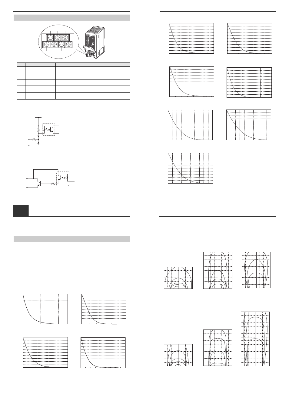
This section describes the static elimination performance of the SJ-M201 Series.
Before you install the SJ-M201 Series, fully calculate the distance between the Static Elimination Head
up to the target object and the time required for static elimination.
About Static Elimination Performance
The following shows a typical example where static is eliminated from an aluminum plate (20 pF) 150 x
150 mm square, charged to +1000 V, by the SJ-M201 Series.
■ Static elimination time
The following graphs show typical examples of the relationship between static elimination time and
static charged voltage.
Measurement condition:
Applied voltage +1000 V
150 mm x 150 mm plate monitor (20 pF) used
Installation distance 300 mm
Air purge pressure 0.5 MPa
Cable length 2 m
SJ-M021
SJ-M021G
SJ-M021+SJ-MS2
SJ-M021+SJ-MS1
0
100
200
300
400
500
600
700
800
900
1000
0
0.2
0.4
0.6
0.8
1
Charged le
v
el (V)
Time (secs)
0
100
200
300
400
500
600
700
800
900
1000
0
0.1
0.3
0.4
0.5
0.6
Time (secs)
Charged level (V)
0.2
0
100
200
300
400
500
600
700
800
900
1000
0
0.2
0.6
0.8
1.2
1
1.4
Time (secs)
Charged level (V)
0.4
0
100
200
300
400
500
600
700
800
900
1000
0
1
3
4
7
6
5
8
9
Time (secs)
Charged level (V)
2
2-1
Before Installation
SJ-M021+SJ-MS3 (500 mm)
SJ-M021+SJ-MS4 (500 mm)
SJ-M021+SJ-ML
SJ-M021+SJ-ML2
SJ-M021+SJ-ML1
SJ-M021+SJ-ML3 (500 mm)
SJ-M021+SJ-ML4 (500 mm)
0
100
200
300
400
500
600
700
800
900
1000
0
1
3
4
6
5
7
Time (secs)
Charged level (V)
2
0
100
200
300
400
500
600
700
800
900
1000
0
1
5
7
11
9
12
Time (secs)
Charged level (V)
3
2
6
8
10
4
0
100
200
300
400
500
600
700
800
900
1000
0
0.2
1
1.4
Time (secs)
Charged level (V)
0.6
0.4
1.2
0.8
0
0.1
0.2
0.3
0.4
0.5
0.6
0.7
0.8
0.9
1
0
0.5
2
Time (secs)
Charged level (V)
1.5
1
0
0.1
0.2
0.3
0.4
0.5
0.6
0.7
0.8
0.9
1
0
0.5
2.5
4
4.5
5
1.5
1
3
2
3.5
Time (secs)
Charged level (V)
0
0.1
0.2
0.3
0.4
0.5
0.6
0.7
0.8
0.9
1
0
0.5
2.5
4
4.5
5
1.5
1
3
2
3.5
Time (secs)
Charged level (V)
0
0.1
0.2
0.3
0.4
0.5
0.6
0.7
0.8
0.9
1
0
1
5
8
9
10
3
2
6
4
7
Time (secs)
Charged level (V)
2-1
Before Installation
■ Static elimination area
The following graphs show the relationship between the time required for eliminating static from a
target object charged between +1000 and +100 V and the distance from the charged object to the
Static Elimination Head.
Model No. SJ-M021
Air flow rate 20 Nl/min
(pressure 0.01 MPa)
Air flow rate 60 Nl/min
(pressure 0.05 MPa)
Air flow rate 250 Nl/min
(pressure 0.5 MPa)
Model No. SJ-M021G
Air flow rate 20 Nl/min
(pressure 0.02 MPa)
Air flow rate 60 Nl/min
(pressure 0.12 MPa)
Air flow rate 200 Nl/min
(pressure 0.5 MPa)
200 150 100 50
0
50 100 150 200
mm
mm
0
200
400
600
100
300
500
0.5sec
1sec
2sec
5sec
10sec
200
100
150
50
50
0
100 150 200
mm
mm
100
0
200
400
500
600
700
800
900
300
1000
0.5sec
1sec
2sec
5sec
200 150 100 50
50
0
100
200
150
mm
mm
300
0
150
450
750
1050
1500
600
900
1200
1350
0.5sec
1sec
2sec
200 150 100 50
0
50 100 150 200
mm
mm
0
200
400
600
100
300
500
0.5sec
1sec
2sec
5sec
10sec
200 150 100 50
0
50 100 150 200
mm
mm
0
200
400
600
100
300
500
800
1000
700
900
0.5sec
1sec
2sec
3sec
-200 -150 -100 -50 0
50 100 150 200
mm
mm
0
200
400
600
100
300
500
800
1000
700
900
1100
1300
1500
1200
1400
0.5sec
1sec
1.5sec