I.c.c. setting – KEYENCE SJ-M201 User Manual
Page 11
11
3-4
Other Functions
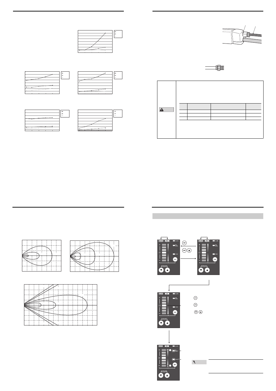
■ Relationship between installation distance and static elimination speed
according to air flow rate
The relationship between static elimination
speed and installation distance between the
Static Elimination Head varies according to
the air flow rate.
Select an air supply flow rate by referring to
the typical example on the right.
Measurement conditions:
Static elimination time from +1000V to +100V
range
150 mm x 150 mm plate monitor (20 pF)
used
0.00
0.50
1.00
1.50
2.00
2.50
3.00
4.00
3.50
0
150
250
50
100
200
Installation distance (mm)
Static elimination speed (secs)
20NL
60NL
250NL
SJ-M021
0.00
1.00
2.00
3.00
4.00
5.00
6.00
8.00
7.00
0
150
250
50
100
200
20NL
40NL
160NL
Installation distance (mm)
Static elimination speed (secs)
0.00
1.00
2.00
3.00
4.00
5.00
6.00
8.00
7.00
0
150
250
50
100
200
20NL
60NL
250NL
Installation distance (mm)
Static elimination speed (secs)
0.00
1.00
3.00
5.00
7.00
9.00
11.00
15.00
13.00
0
150
250
50
100
200
60NL
140NL
250NL
Installation distance (mm)
Static elimination speed (secs)
0.00
1.00
3.00
5.00
7.00
9.00
11.00
15.00
13.00
0
150
250
50
100
200
20NL
60NL
250NL
Installation distance (mm)
Static elimination speed (secs)
SJ-M021+SJ-MS1
SJ-M021+SJ-MS2
SJ-M021+SJ-MS3 tube 500 mm
SJ-M021+SJ-ML
3-4
Other Functions
■ Relationship between installation distance and wind speed according to air
flow rate
The relationship between wind speed and static elimination head installation distance varies
according to the air flow rate.
Adjust the air supply flow rate by referring to the following figures.
75
100 150 200 250 300 350
50
0
400mm
mm
50
25
0
-25
-50
-75
10m/s
2m/s
1m/s
75
200 300 400 500 600 700
100
0
1000mm
mm
50
25
0
-25
-50
-75
800 900
10m/s 5m/s
1m/s
2m/s
100
200 300 400 500 600 700
100
0
1500mm
mm
50
75
25
0
-25
-50
-75
-100
800 900 1000 1100 1200 1300 1400
10m/s
20m/s
5m/s
1m/s
1m/s
2m/s
2m/s
Air flow rate: 250 Nl/min (pressure 0.5 MPa)
Air flow rate: 20 Nl/min (pressure 0.01 MPa)
Air flow rate: 60 Nl/min (pressure 0.08 MPa)
3-4
Other Functions
■ How to supply air
Supply air from the SJ-M021(G)'s Air Input Unit as shown in
the figure on the right.
Joints and tubes must be prepared separately.
●
Recommended joint
We recommend using a tube fitting (tube dia. 6 mm, 8 mm) made by PISCO for a joint to the Air Input
Unit.
Rc1/8
Tube
• Be sure to limit the tightening torque to 0.7 Nm. Tightening beyond this
limit may cause an accident or a malfunction.
• Use clean air, without dust or oil mist, when measuring. (When
compressed air is used, air that conforms to ISO class of 1.1.1 through 1.3.1
is allowable.)
Class rate of compressed air indicated by ISO 8573-1
* Water content values shown in the bracket indicates the dew point temper-
ature at atmospheric pressure.
E.g. The “Class 1.3.1” indicates the rating of 0.1 μm of the solid particle.
-20°C of dew point under the pressure and 0.01 mg/m
3
oil density.
Tube dia.6 mm: PC6-01
Tube dia.8 mm: PC8-01
CAUTION
Class
Maximum particle
size (μm)
Water content (Pressure dew
point temp. at 0.69 MPa)
Remained oil
(mg/m
3
)
1
0.1
-70 (-83)
0.01
2 1
-40
(-58)
0.1
3 5
-20
(-42)
1
3-4
Other Functions
I.C.C. Setting
The I.C.C. (Ion Current Control) can be turned on and off.
Turning off the I.C.C. allows the ion balance adjustment function to generate positive and negative
ions at a fixed ratio.
Either is lit
Blink alternately
Hold down
for at least
1 second
Hold down for at
least 1 second
simultaneously
Change
Change
Change
Blink
Blink
Change the 4th LED from the top in the Setup mode.
Press for a short time
: advances to the Setup mode
of the selected item
Hold down for at least 1 second: exits the Setup mode and
returns to the Run mode
: moves the cursor up and
down
On the ion monitor, the currently selected items are lit in green and the
items whose default have been changed are lit in red.
I.C.C. is set at ON by default setting.
Items that satisfy both of these conditions blink in red and green
alternately.
Advance to the I.C.C. ON/OFF setting from the Setup mode in page 8,
and select either of the following:
(1) I.C.C. ON (Default)
(2) I.C.C. OFF
Select an appropriate nozzle according to the
head. Incorrect setting may cause accidents or
malfunction. When I.C.C. function is off, the ion
level alarm will not be output correctly.
Point